Tessellating CAD Models - Adaptive Mode and Grid Mode
Introduction
During this tutorial, we will learn how to turn a CAD model into a tessellated 3D model – meaning, a 3D mesh model that consists of polygons and can therefore be rendered in nearly all 3D software out there, used for CGI, shown in real-time on mobile devices, and so on.
Concretely speaking, CAD models consist of parametric surfaces called Breps ("boundary representation"), and we will see how to turn these surfaces into polygons – this process is commonly called "tessellation". Since the conversion to polygons is turning infinitely smooth CAD surfaces into new, faceted polygon surfaces, the resulting 3D model can have notable deviations from the original CAD. Therefore, precision during tessellation is quite important. However, at the same time, it is also important to keep our tessellated model lightweight enough and easy enough to work with in any following steps, which is why tessellating with too much detail (too many fine polygons) can also be counter-productive for your workflow. In the next section, we will see how to explore this balance in detail, by choosing a resolution level, and a method to be used, for the tessellation step.
Adaptive Mode and Quick Resolutions
The easiest way to get started with importing and tessellating a CAD model is by dragging a CAD file (for example, a Solidworks, STEP, Rhino or JT file) into RapidPipeline Twin Studio's 3D window. This will open a dialog widget with import options. Alternatively, you can also use the "File" menu and choose the "Import" sub-menu. No matter which of the two methods you choose, the import dialog should look like this:
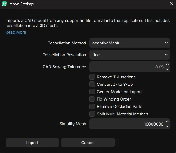
Import dialog with CAD import settings and post-processing options
Depending on the file format that you are importing, these options might look different. They should look like the above for all CAD files, but for 3D file formats like glTF, USD or FBX, you'll have different options – for example, because these formats might not require tessellation.
As you can see, when importing a CAD file, there is a dropdown box for the "Tessellation Method", and the default value is called "adaptiveMesh". Let's keep this one for now and try it out!
The "adaptiveMesh" setting will tessellate (turn into polygons) each part of the CAD model in such a way that the polygons cover all the details, but they won't necessarily be forming any regular pattern or grid (there is another option that achieves that, and we'll look into that later). Instead, by being adaptive, the "adaptiveMesh" method gives you a great, accurate result for the polygon mesh that looks as close as possible to the original CAD surfaces, using an optimized number of polygons. So, if you have a detail somewhere, for example, that detail will use more polygons, and if a part of the surface is flat, it will be accurately represented with just a few polygons instead.
Now, you will see that there are a couple more import options. Most of these you can leave as they are for now, as some of them (like "Fix Winding Order" or "Remove Occluded Parts") allow you to simply apply some operations already during import, as post-processing steps. However, you can also do that at any point later in RapidPipeline Twin Studio. So for now, we can skip these and simply focus on the tessellation part, to learn how it behaves and what results it produces by just tessellating the CAD surfaces into a polygon mesh.
There is one more high-level setting worth noting at this point, which is called "Tessellation Resolution". You will see that there are different quick options, such as "fine", "medium" or "coarse", but also a "custom" option. We will check what the "custom" option can do later, so for now let's leave it at the default ("fine") and press "Import":
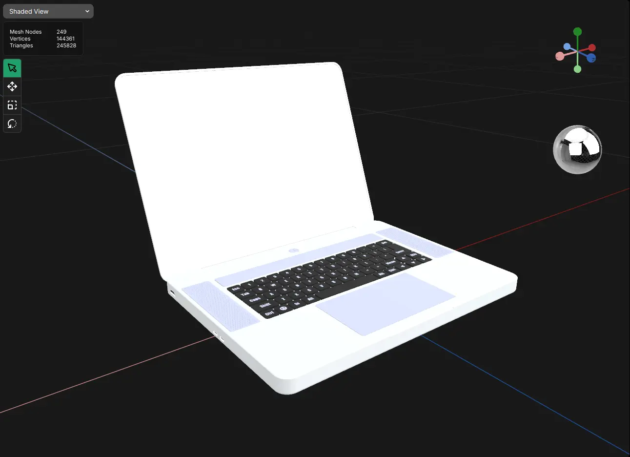
CAD model import, after using "adaptiveMesh" tessellation with the "fine" preset
As you can see, the model in this example got imported with 245K polygons, and it captures the details of the CAD model quite accurately. You can see the number of polygons in the top left view, including an option to select different shading modes. That way, you can explore how the overall shape looks ("Shaded View"), but also how the individual polygons of the mesh are organized ("Wireframe on Surface"):
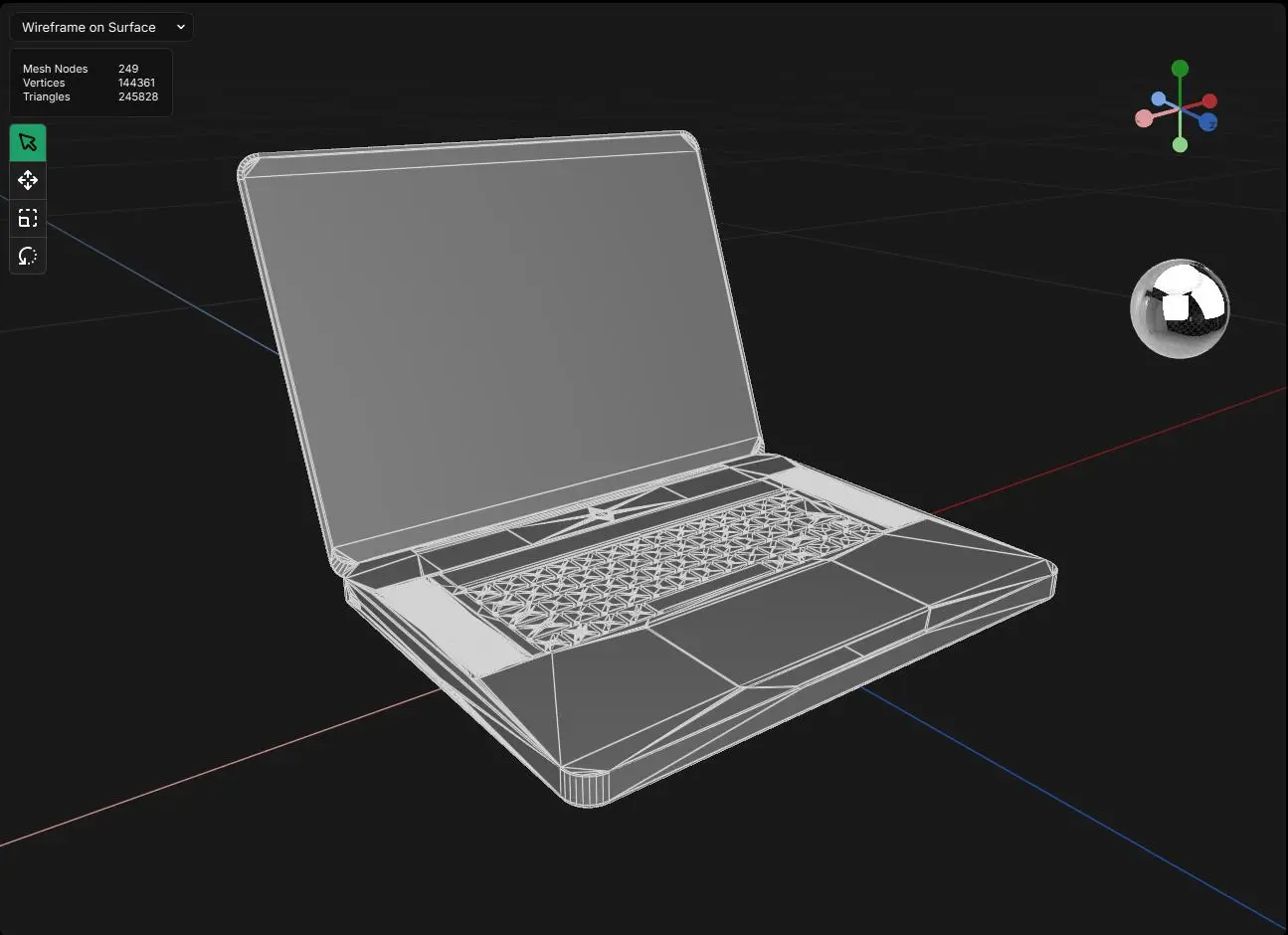
The same result as before, but viewed in "Wireframe on Surface" mode.
Now, let's import the same model again, but this time we choose another value for "Tessellation Resolution" – for example, "coarse". The result should then look like the following:
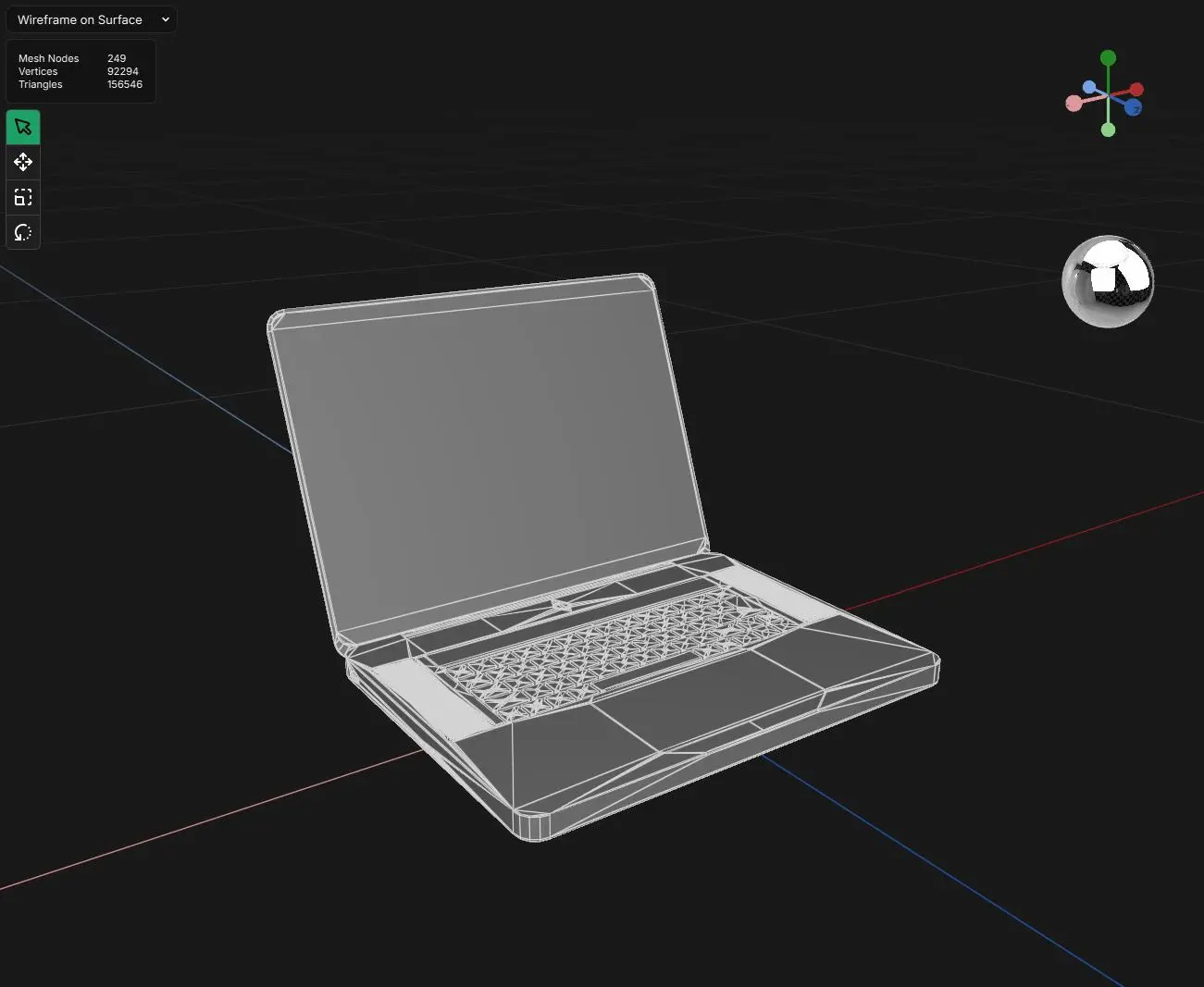
The same CAD model, but this time imported using the "coarse" resolution preset (using shading mode "wireframe on surface")
You will notice that the polygon count is smaller for the "coarse" mode, which makes the model more lightweight to work with, and more lightweight to transmit, for example. At the same time, it will have a little less detail, say, around curved areas, compared to the "fine" preset.
Depending on your 3D CGI or XR application, this might already be a great 3D model to work with. So, if you made it so far, congrats – you have just tessellated your first 3D model with RapidPipeline Twin Studio!
Grid Mode
Sometimes, the adaptive resolution of the tessellation that we have used in the previous section is not what the user or application requires. Instead, for use cases like simulation, but also to facilitate certain manual editing operations, it can be beneficial to have a more regular tessellation, instead of using an adaptive one. For this purpose, RapidPipeline has an option called "regularizedGrid", which you can select in the "Tessellation Method" dropdown box during import. If we do this with the CAD model from the previous example, using the "fine" resolution preset, the result will look like this:
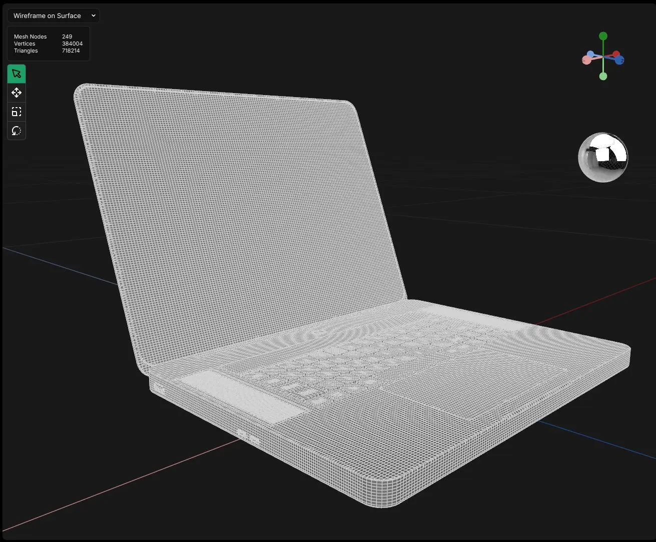
The same CAD model, but this time imported using the "fine" resolution preset with the "regularizedGrid" tessellation method (using shading mode "wireframe on surface")
Just like for the "adaptiveMesh" mode, we can also use "regularizedGrid" with various resolution presets. So if we use the "coarse" resolution preset instead, for example, the resulting 3D model should look like the following:
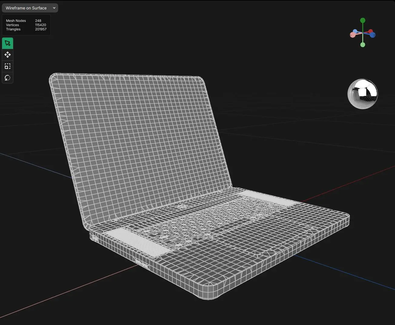
Tessellation using "regularizedGrid", but this time imported using the "coarse" resolution preset (using shading mode "wireframe on surface")
With this toolkit at hand, you will already be able to address many use cases. Within the next sections, we will go even deeper and see how you can tweak the tessellation results even further, if desired.
Custom Tessellation Settings
In case you'd like to have even more control over the tessellated result, you can also drive both tessellation modes ("adaptiveMesh" and "regularizedGrid") with a "custom" tessellation resolution, which will allow you to set more expert settings, once selected as a choice under "Tessellation Resolution".
In general, for both tessellation modes, you can set sewing tolerance and t-junction removal, which define how the tessellator handles sewing of nearby CAD surface patches and t-junctions in the topology.
Apart from these detailed options, adaptive mesh lets you define surface deviation and max. surface angle:
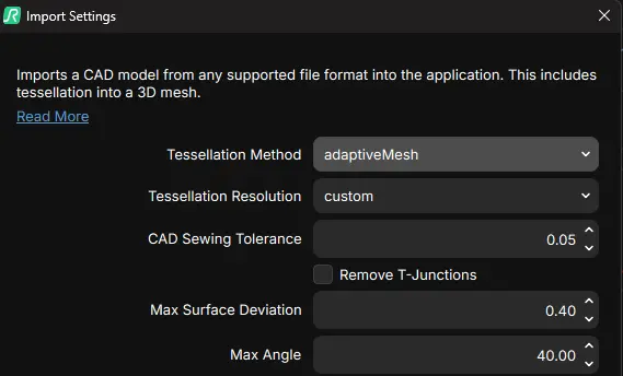
Custom options for the "adaptiveMesh" tessellation method.
As you can see in the following, these two settings are related to precision of the tessellation. Deviation measures, as a distance, how far the tessellated mesh is allowed to deviate from the original CAD surface, and angle tolerance defines in how much detail curved areas are tessellated (which matters for shading, for example):
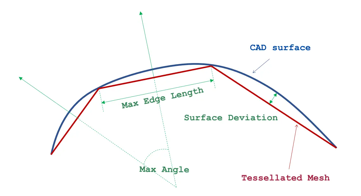
Tessellation aspects: deviation measures, as a distance, how far the tessellated mesh is allowed to deviate from the original CAD surface, and angle tolerance defines in how much detail curved areas are tessellated (which matters for shading, for example).
In contrast, when using the "regularizedGrid" method, you will see different tessellation settings:
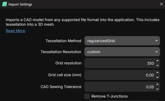
Custom options for the "regularizedGrid" tessellation method.
Since the grid-based tessellation is designed to create regular grid patterns, you can configure it to use either a certain grid resolution (e.g., 200x200x200 cells), or you can prescribe a maximum grid cell size, which will then be kept by the tessellator. Note that a value of zero for the max. grid cell size will not have any effect, whereas small values will potentially lead to very densely tessellated areas.
With this advanced toolkit at hand, you will now be able to tessellate CAD models in a custom way that works best for your use case.