3D Processor - 3D Edit

3D Edit
RapidPipeline 3D Processor has advanced tools for manipulating the shading of 3D meshes. Smooth/hard edges can be modified, UVs can be generated, new materials can be assigned, assets can be re-centered, and more.
Mesh Normals
Mesh normals control the shading of meshes. There are two controls here: the Normal Hard Angle Threshold, and the Normal Computation Method.
These two controls work independently from each other... the Threshold controls which edges are marked "hard", while the Method affects the directions of the "soft" normals.
Normal Hard Angle Threshold
The threshold is specified in degrees and is used for splitting vertex normals, which controls which edges should be changed into soft or hard. This is an easy way to break up blobby shading, by adding sharp edges.
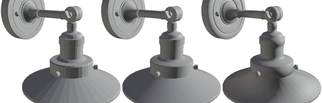
Normal Hard Angle Threshold at 0 degrees, 60 degrees, and 180 degrees.
- 0 = All edges become sharp. This is essentially flat shading.
- 60 = The model will get hard edges where ever neighboring faces are angled more than 60 degrees from each other. This is the default value.
- 180 = All edges become soft.
Normal Computation Method
The method affects how the angles of the normals for soft edges are handled.
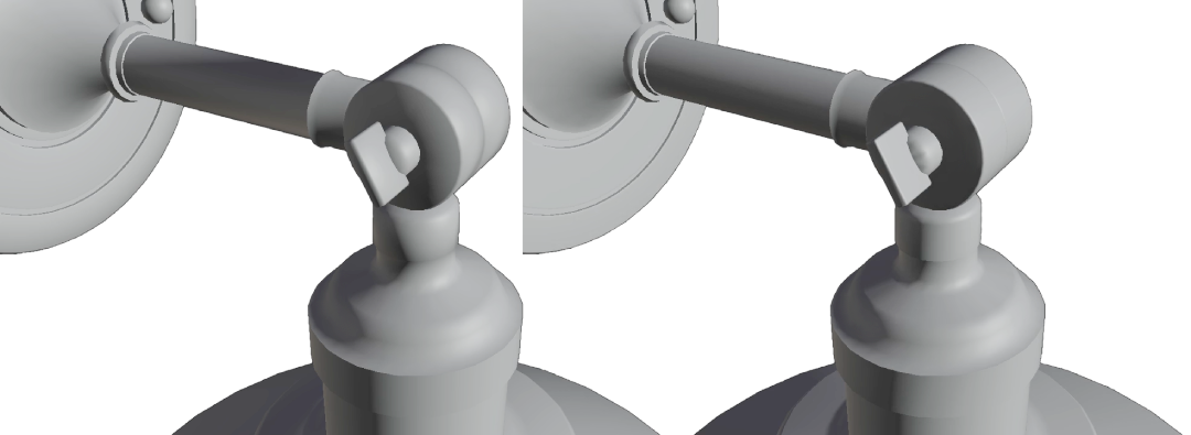
Normal Computation Methods: Angle (left) and Area.
- Angle: The angles of normals are averaged across all edges. This works well for most surfaces, including organic models.
- Area: This weights the normals more towards the larger faces. This works especially well when a model has bevels or fillets. This method is sometimes called "face-weighted normals".
Model Edit
These settings are applied just before Export. Changes made here do not affect other processing methods, for example any operations which rely on units or the size of the bounding box are done using the transform matrix of the incoming assets.
Scaling Factor
Assets can be scaled before Export. A value of 1.0 means no change is applied.
Center Object
Assets can be re-centered before Export.
- Center = The asset is centered on the world origin.
- Rear Center = The rear center of the asset is placed at the world origin.
- Bottom Center = The bottom center of the asset is placed at the world origin.
- Top Center = The top center of the asset is placed at the world origin.
Material Edit
Materials and UVs can be replaced, optimized, or refined.
Alpha Conversion
Materials using transparency can be converted to opaque, or to use alpha mask instead of blend.
These conversions are particularly helpful for assets produced with Clo3D or Browzwear, which use alpha blend for mesh fabrics and decals.
Alpha blend often causes sorting errors in real-time renderers, where far surfaces are rendered in front of near surfaces. Alpha mask avoids these issues, at the expense of allowing only on/off transparency.
Converting alpha blend to opaque can also be useful, when textures are using alpha channels that contain only white pixels. In this case, alpha blending is superfluous and can be disabled entirely.
A threshold can help preserve transparency for surfaces that may benefit from keeping a low amount of blend, for example semi-transparent glass or plastic.
- Alpha Blend to Mask Conversion = Change the material to alpha mask if the alpha blend seems to be using mostly high contrast values. Conversion becomes more aggressive as the threshold is decreased. 1.0 changes no materials, 0.0 changes all materials to alpha mask.
- Alpha to Opaque Conversion = Change the material to opaque if the alpha seems to be opaque; i.e. mostly white. Conversion becomes more aggressive as the threshold is decreased. 1.0 changes no materials, 0.0 changes all materials to opaque.
Material Replacer
Allows for replacing materials with default materials or replacing texture maps with values. This can help if an asset has no materials, or materials have been inconsistently applied.
Default Material
New basic PBR materials can be generated for all surfaces.
- Base Color = A new base color can be specified. This can include an alpha value, however alpha is not enabled for the resulting material. Alpha blending should be applied judiciously as it often causes sorting errors in real-time renderers.
- Metallic = A new metallic value can be specified. In PBR material models, metallic is best at either 1.0 or 0.0 since in-between values tend to cause unpredictable non-physical behavior.
- Roughness = A new roughness value can be specified. Roughness is an approximation of micro-surface facets, with zero being completely glossy and 1 being completely rough.
Generate UVs
New UVs can be generated for all meshes in the asset. These UVs replace any existing texture coordinates, and are stored in UV0.
Cube Unwrapping
New UVs are generated using three planar projections.
The scale of the projections can be adjusted: 1.0 means the UV will be 1 meter square. As the scale is increased, the UVs will tile more, and the texture will appear smaller. Decreasing the scale causes the texture to appear larger.
- To apply Real-World Scale of 1 unit = 1 centimeter, use 100, which is how many centimeters there are in a meter.
- To apply Real-World Scale of 1 unit = 1 inch, use 39.37, which is how many inches there are in a meter.
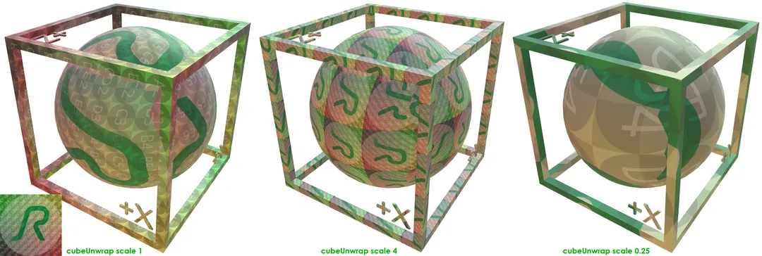
A 1-meter box and sphere showing Cube Unwrap Scale: 1 (left), 4, and 0.25.
Add Checker Texture
This will add a 1024x1024 JPG checker texture into the Base Color input of the material.

The 1024x1024 checker texture.
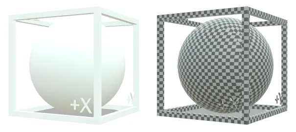
A 1-meter box and sphere without the checker texture (left), and with the checker texture at Cube Unwrap Scale 0.25.
Drop Uniform Texture Maps
Flat-color or nearly-flat-color textures can be automatically culled from materials, and a number for the average value will be used instead. This can dramatically reduce file sizes and draw calls.
A threshold can be used to influence how "empty" a texture needs to be before it is culled.
- Zero disables culling; set the threshold more than zero to enable culling.
- A threshold of 0.01 means there must be no more than 1% difference between all pixels for a texture to be culled.
- A threshold of 1 means all pixels in the texture may have 100% difference and they will still be culled, so all textures are removed regardless of how much texture information is present.
To apply culling to all textures, increase the Default Texture Map Threshold to be more than zero.
To apply culling only to specific texture inputs, increase the threshold for specific texture types.
Repair
Vertex Merging
Merges close vertices with a given threshold.
Vertex Merging Per Mesh decides if vertex merging should only be performed within each mesh node (on) or across all nodes (off).
There are two choices for controlling the merging distance:
- Vertex Merging Distance Percentage - Percentage distance for vertex merging.
- Vertex Merging Distance Value - Value in scene units for vertex merging.
Fix Winding Order
Automatically flip the winding order of triangles or parts (mesh lumps) according to certain metrics.
There are two choices for controlling the visibility calculation:
- Visibility Mode: default
- Visibility Mode: mesh
Further Documentation
For the full Documentation on all available data operations commands and system settings, please refer to the CLI Commands Guide and 3D Processor System Schema & Settings.
The 3D Processor is available for multiple interfaces: