3D Processor - Scene Graph Flattening

Scene Graph Flattening
The scene graph is a list of all the nodes in the asset, including meshes, cameras, lights, materials, etc. These nodes may be linked in a hierarchy, with parent-child relationships that affect their inherited transforms.
RapidPipeline 3D Processor's Scene Graph Flattening only applies to mesh nodes. Four unique flattening modes allow the graph to be intelligently simplified by combining and splitting nodes based on shared properties.
Reducing the number of mesh nodes can help improve performance (primarily by reducing draw calls), but can also improve decimation and other actions by allowing multiple surfaces to be treated together during processing.
Some formats (e.g. OBJ) do not support hierarchies or instances. For these formats, our exporters do their best to at least keep individual meshes.
Flattening Method
Several methods are provided for controlling how nodes are combined.
None
No flattening will be applied, the scene graph will remain the same as in the input. This mode produces the highest number of draw calls, but it preserves all nodes and any instancing if present.
Full
All meshes will be combined into a single mesh, using a single material. If the input meshes use different materials, the properties and textures will all be combined into a single shared material.
By Opacity
Meshes all non-transparent meshes together into a single mesh, and keeps all the transparent meshes separate. Transparent meshes are not combined together, because often this improves depth sorting in real-time rendering.
By Material
Meshes using the same material will be combined together. This can change the number of meshes, but will keep the same number of materials as the input.
Auto
Let RapidPipeline 3D Processor decide. At the moment, this is the same as using By Opacity.
Material Merging
Material merging is automatically handled when nodes are flattened, depending on the mode. By Opacity, Auto and Full will automatically merge materials as needed.
Benefits and Drawbacks of Not Flattening
Not using any flattening has specific benefits and potential downsides, depending on what mode is chosen for the specific input mesh.
Benefits:
Individual nodes and subtrees can continue to be selected and processed within your optimized model.
If the input contains instances of meshes, they can be maintained as instances and stored/rendered efficiently. Flattening tends to remove instancing.
If the input contains transparent meshes, the renderer will likely be able to render them in the correct order, even after optimization.
Potential Downsides:
More complex files, and possibly larger file sizes.
More draw calls, leading to reduced rendering performance if the model has large numbers of nodes and meshes.
Some operations like decimation may behave in unexpected ways, e.g. create cracks between unconnected but aligned meshes. Flattening meshes before decimation can help prevent this.
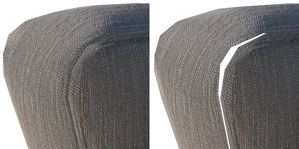
Merging meshes together will help prevent gaps from appearing between them when they are optimized. Scene Graph Flattening byMaterial (left), versus None (right). See Tutorial: CLI Preserve UVs for a step-by-step tutorial.
Flattening Examples
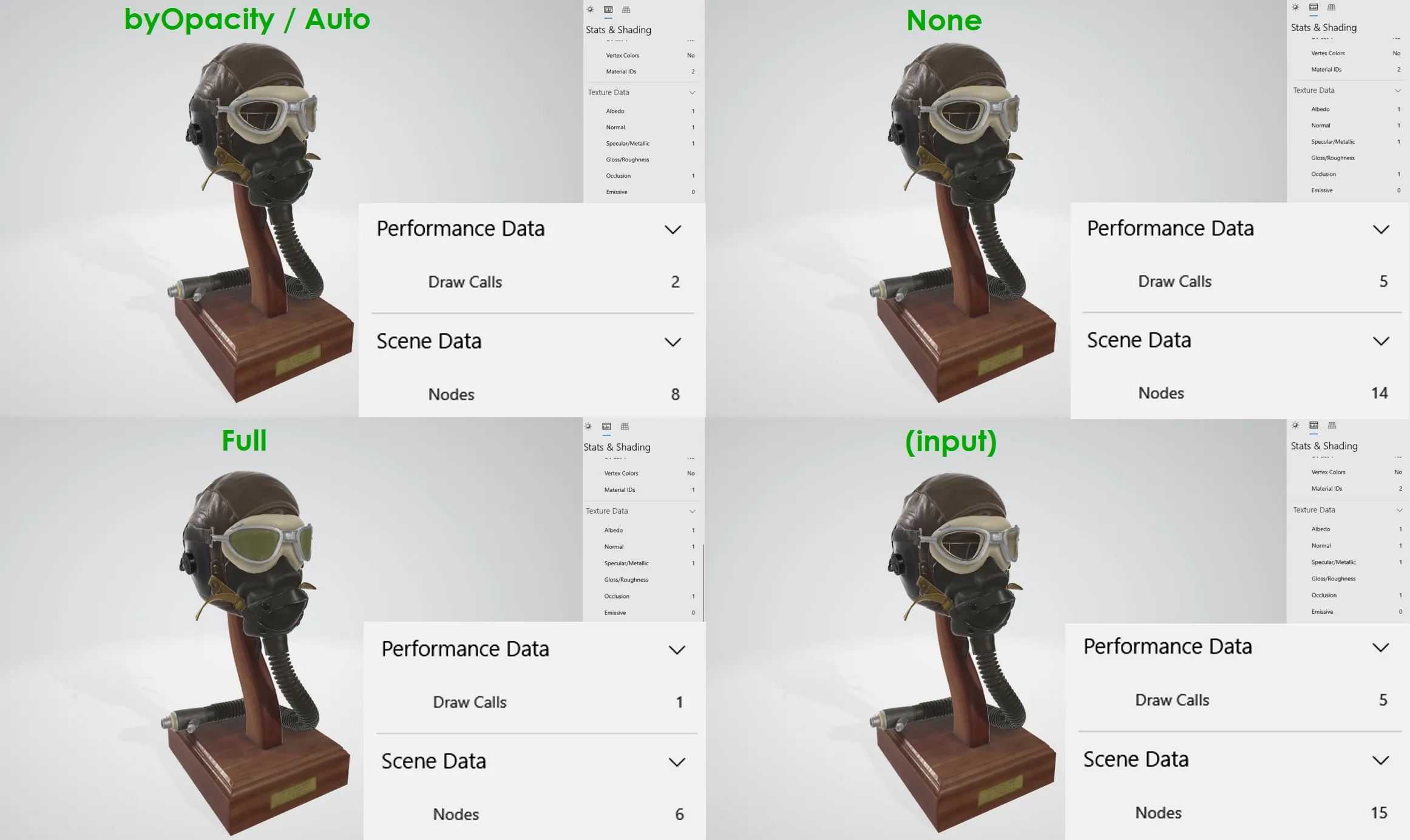
Flattening applied to the model FlightHelmet.glTF. Top-left: flattened "byOpacity"/"auto"; Top-right: flattened "none"; Bottom-left: flattened "full"; Bottom-right: original.
When comparing modes, each output has a different number of draw calls and nodes:
Flattening mode "full" in the bottom left corner lost the transparency because full disregards transparency. This can be particularly useful for distant LODs (level of detail models).
Flattening mode "byOpacity" produces two draw calls from two different meshes so that the transparent glasses and the opaque parts can be rendered correctly. If the opaque parts used alpha, most real-time renderers would cause noticeable sorting errors, thus it's usually best to keep them separate.
Flattening mode "none" has almost the same result due to the structure of the input mesh. Note this will differ depending on the organization of the input mesh and hierarchy.
Flattening mode "auto" produces results supporting and preserving transparency without compromising the performance too much. An input file with a lot of unique transparent parts will have more draw calls than with the full flattening mode, but the consequences regarding performance are often still minor. Usually the benefits of preserving transparency should outweigh the additional draw calls and nodes.
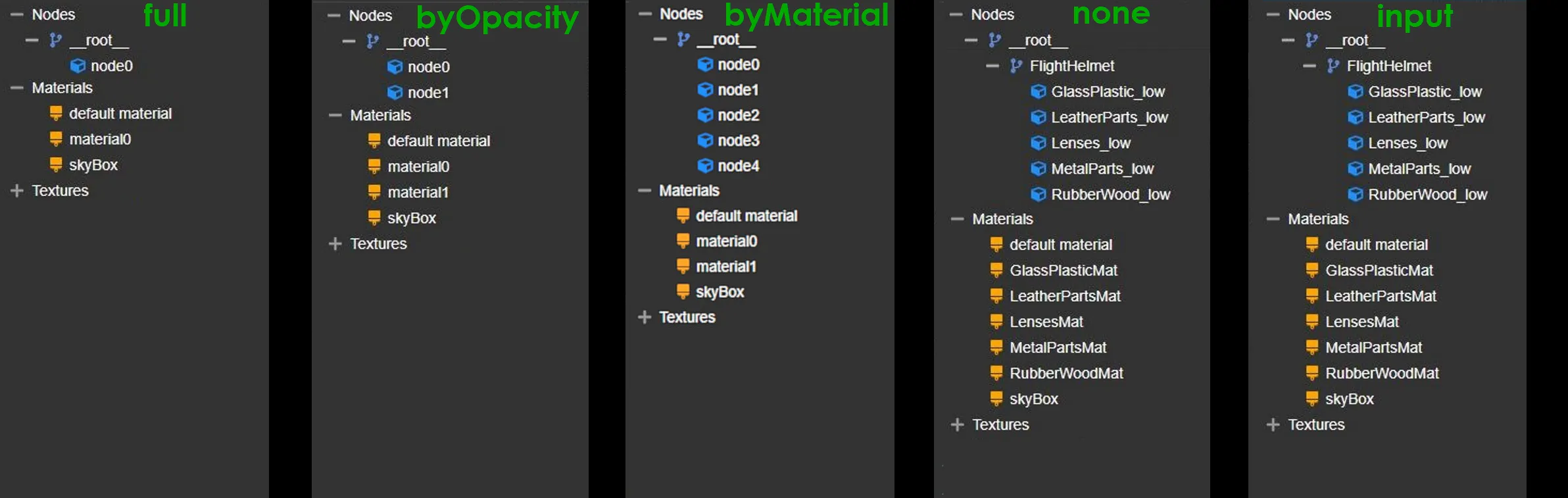
From left to right: "full", "byOpacity"/"auto", "byMaterial, "none", and the original input.
The hierarchies of the generated results give a good overview on how RapidPipeline can use a grade of flattening specifically tailored to the needs of each final application.
The flattening mode "none" will preserve the nodes and naming conventions of the original, whereas "full" and "byOpactiy" modes will flatten either everything or all opaque nodes, respectively.
The "byMaterial" mode will usually produce a different number of nodes than given in the input model. The only difference between "byMaterial" and "byOpacity" is that the latter will merge together all nodes that have the same opacity category (transparent or opaque), while "byMaterial" merges together all nodes that have the same material.
The flattening mode "none" will preserve Material IDs. However if the input materials are using textures on one or multiple atlases, RapidPipeline will always re-bake all materials on a number of atlases defined by the given atlas mode setting.
To simplify the model but also preserve all original texture maps and UV coordinates, in the Decimator choose the option Keep Materials and UVs. This will preserve tiled textures, and optionally add a 2nd UV channel for non-tiled ambient occlusion.
Preserved Scene Depth Level
This number acts as an overall limit, preserving a minimum number of scene graph levels, by allowing some nodes to be combined while preserving others based on their level in the hierarchy.
Zero is the default, meaning no limits will be applied, so the flattening of the scene graph will be fully controlled by the flattening mode. Increasing the Preserved Scene Depth Level will increase the number of levels to be preserved.
Preservation Examples
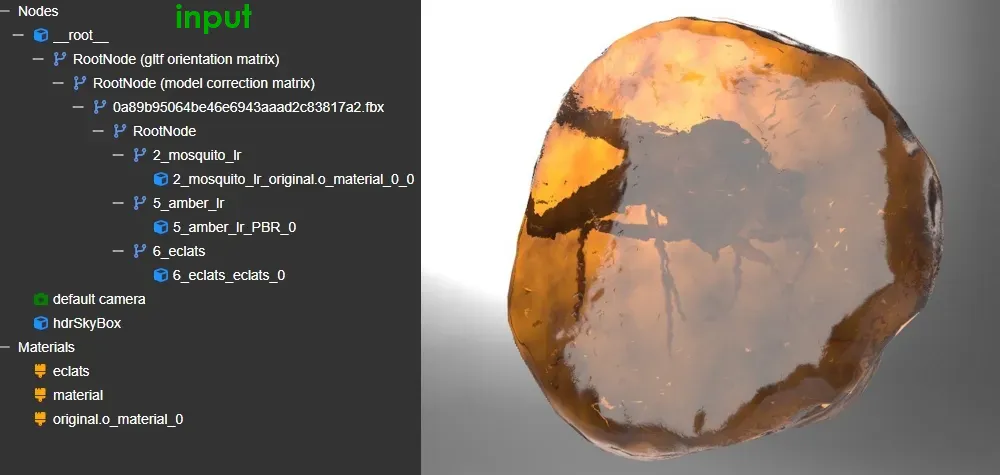
The input scene graph for MosquitoInAmber.glb.
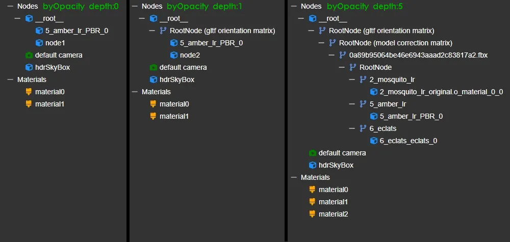
After processing with flattening mode byOpacity, and increasing the preservation level, sceneDepth 1 and 5 have a very distinguishable effect on the scene graph. Note that material names are not preserved, as these might tend to be merged depending on opacity.
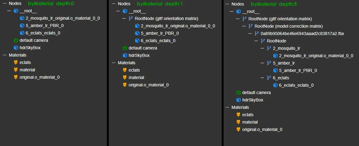
If the same levels are used with flattening mode byMaterial, this will preserve all materials and their names.
Further Documentation
For the full Documentation on all available data operations commands and system settings, please refer to the CLI Commands Guide and 3D Processor System Schema & Settings.
The 3D Processor is available for multiple interfaces: