Tutorial: 3D Processor CLI Decimation
| This tutorial contains these key points: |
|---|
| ✔️ Import a 3D model |
| ✔️ Create a Settings Preset Config |
| ✔️ Decimate a 3D model |
| ✔️ Output a glTF file |
| ✔️ Compare the results |
This tutorial shows how to use RapidPipeline 3D Processor CLI to optimize a 3D model into a lower triangle count, how to create and use a Settings Preset Config file, and how to evaluate the output results.
RapidPipeline 3D Processor is a powerful 3D data optimization and automation toolset; for more information please see the product overview.
How Decimation Works
Decimation is a common method to optimize a 3D asset, by reducing the geometric complexity.
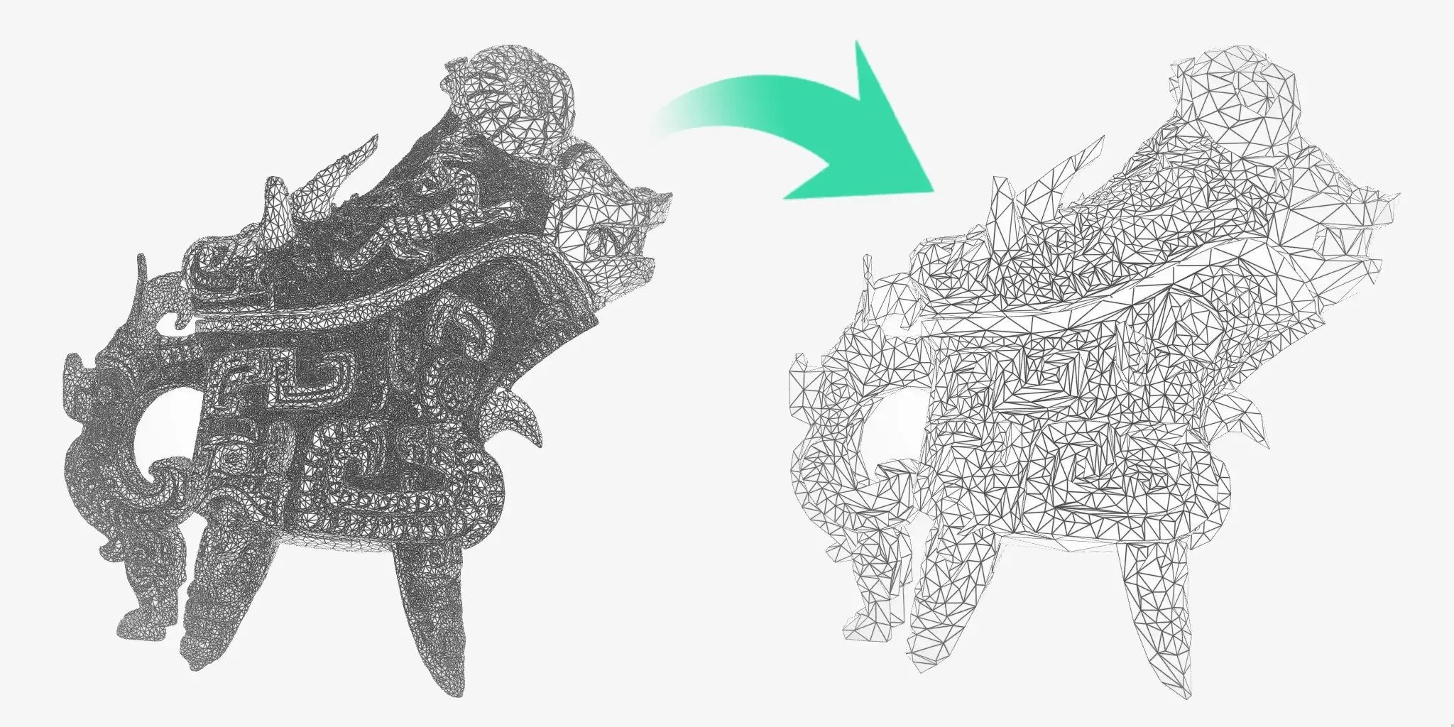
RapidPipeline can collapse edges to achieve a number of triangles, a number of vertices, a deviation threshold from the input topology, or a resolution which depends on the size on screen. This tutorial explains how to decimate using a desired triangle count.
Please see the reference documentation for additional information about decimation targets including the size on screen modifier.
By default, decimation will automatically create new UV coordinates, and automatically bake textures from the input model into a new layout. This default behavior can be overridden if desired. To learn how to preserve tiled UVs, please see Tutorial: CLI Preserve UVs.
To control the decimation process, a Settings Preset Config is required. This is a text file with a specific layout, containing settings that can be edited as needed.
Config files can be created in multiple ways: by using the CLI, or using the Blender Plugin, or using the Web Platform, or using the REST API. In this tutorial, a minimal Config will be created by copying and editing an existing code sample in the reference documentation.
Decimating the 3D Model
| To create and use a minimal Settings Preset Config with CLI 7.x: |
|---|
| 1. Download a 3D asset, for example RitualWineEwer.glb (8.5mb). This is a CC0 Public Domain model from The Smithsonian Institution which has 197,176 triangles (source). |
2. Create a new text file in the same folder as a 3D asset, named decimate.json. This will be the Config file. |
| 3. Copy the sample JSON settings code from the Decimator documentation page and paste it into the new file. |
4. Edit the line "value": 1 from the default lowest value into a reasonable triangle amount for the asset, like "value": 10000. |
| 5. Save the edited Config file. The finished file can alternatively be downloaded here. |
| 6. In the same folder containing the 3D model and the Config, open a Windows PowerShell. This can be done by holding the Shift key, right-clicking in the folder, and choosing Open PowerShell window here. |
| 7. Type (or copy-paste) the CLI command below, and press the Enter key. |
rpdx -i RitualWineEwer.glb --read_config decimate.json -r -o out
The results in the CLI:
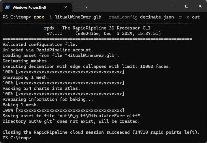
CLI output from the decimate process
CLI Commands Explained
| Command | Result |
|---|---|
rpdx | Starts the CLI |
-i RitualWineEwer.glb | Imports the 3d asset for processing |
--read_config decimate.json | Loads the Settings Preset Config file (created above) |
-r | Runs the 3D Processor |
-o out | Outputs the processed 3D asset into a folder named \out |
Understanding the Outputs
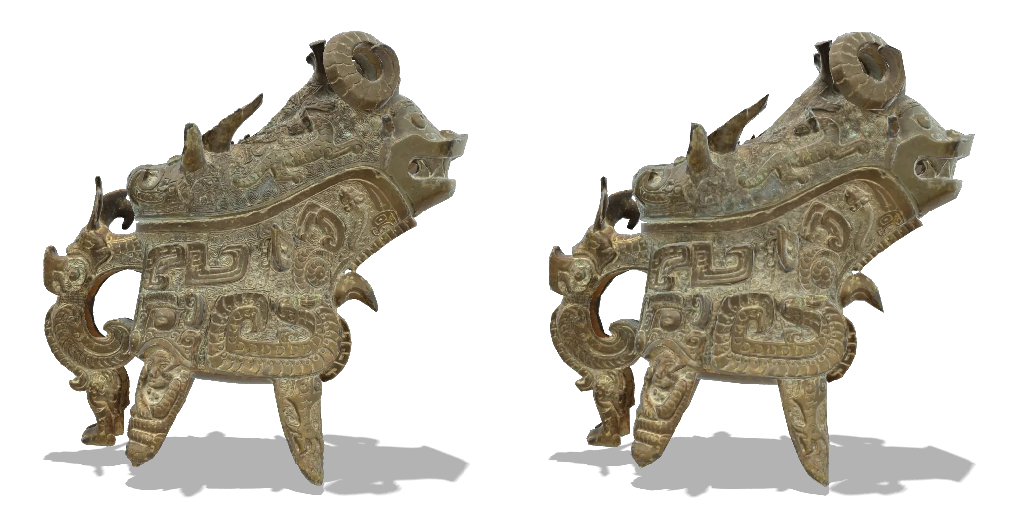
PBR renders of the input model (left) and output model (right) are virtually identical
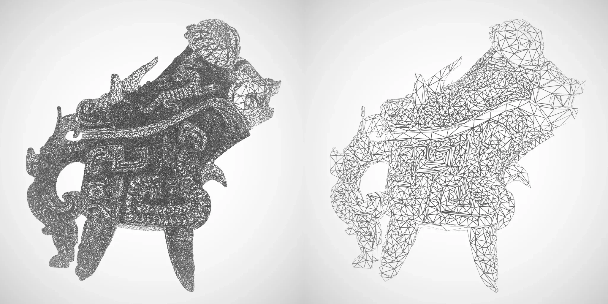
Wireframe renders of the input model (left) and output model (right)
The output file is saved into a subfolder named \out\0_gltf. A numbered subfolder is created because an Output command can save multiple file formats in the same command, so each is saved into its own folder, to avoid conflicts.
The output filename will use the same prefix as the input file RitualWineEwer but in this case it has a different file extension .gltf. This is because the default export behavior is to create a .glTF file, with external references for the geometry (.BIN) and textures (.JPG). Output formats can be customized as desired by editing the Config file.
GLB and glTF files contain the same data; a .GLB is a self-contained single binary file, which makes it easier to share with others. A .glTF file exposes the model parts as separate files, which makes it easier to understand the separate ingredients.
The input model has two materials; these were merged into one material for the output file. The default behavior is to merge materials per mesh, but this can be changed if desired.
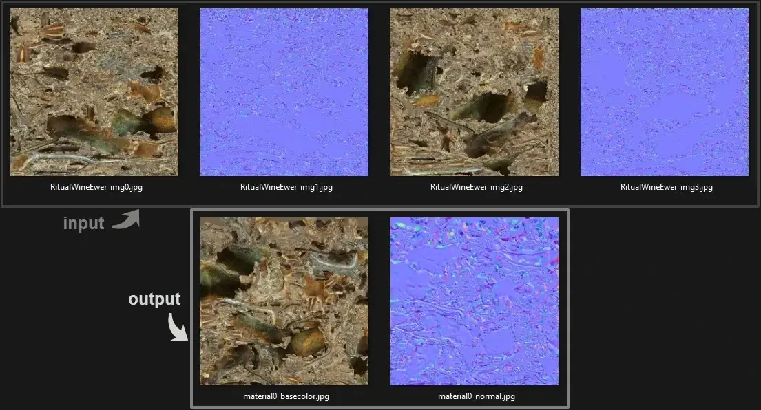
Two materials in the input were merged into one material for the output
Material merging is controlled by Scene Graph Flattening, which works in conjunction with Material Merger to combine materials during optimization. The behaviors for these can be controlled via the Config file.
Input / Output Statistics
| Input Asset | Output Asset |
|---|---|
| 197176 triangles | 10000 triangles |
| 2 materials | 1 material |
| 2 BaseColor maps | 1 BaseColor map |
| 2 Normal maps | 1 Normal map |
| Draco mesh compression | No mesh compression |
| File size 8.5 mb | File size 3.5 mb |