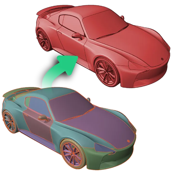
Import Settings Guide
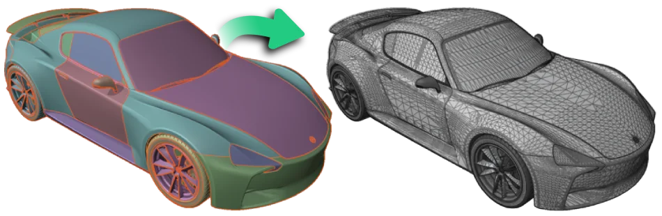
A car CAD assembly, imported and tessellated.
General Import Settings
The following settings are applied to all assets on import, regardless of file format.
| Setting Title | Setting Name | Level | Type [Range] (Default) | Description |
|---|---|---|---|---|
| Convert Z- to Y-Up | rotateZUp | basic | boolean (false) | turns rotation to z-axis pointing upwards on/off |
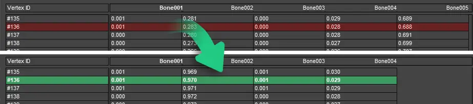
| Fix Animation Data | fixAnimationData | advanced | boolean (true) | cleans up weights so they sum up to 1 and assigns bone 0 for 0-weights |
| Normal Map Y Flip | normalmapYFlip | expert | boolean (false) | flip normalmaps Y axis on import. Only affects fbx data. |
Examples: | JSON | WebUI | PluginUI |
- 🖹 JSON Settings File:
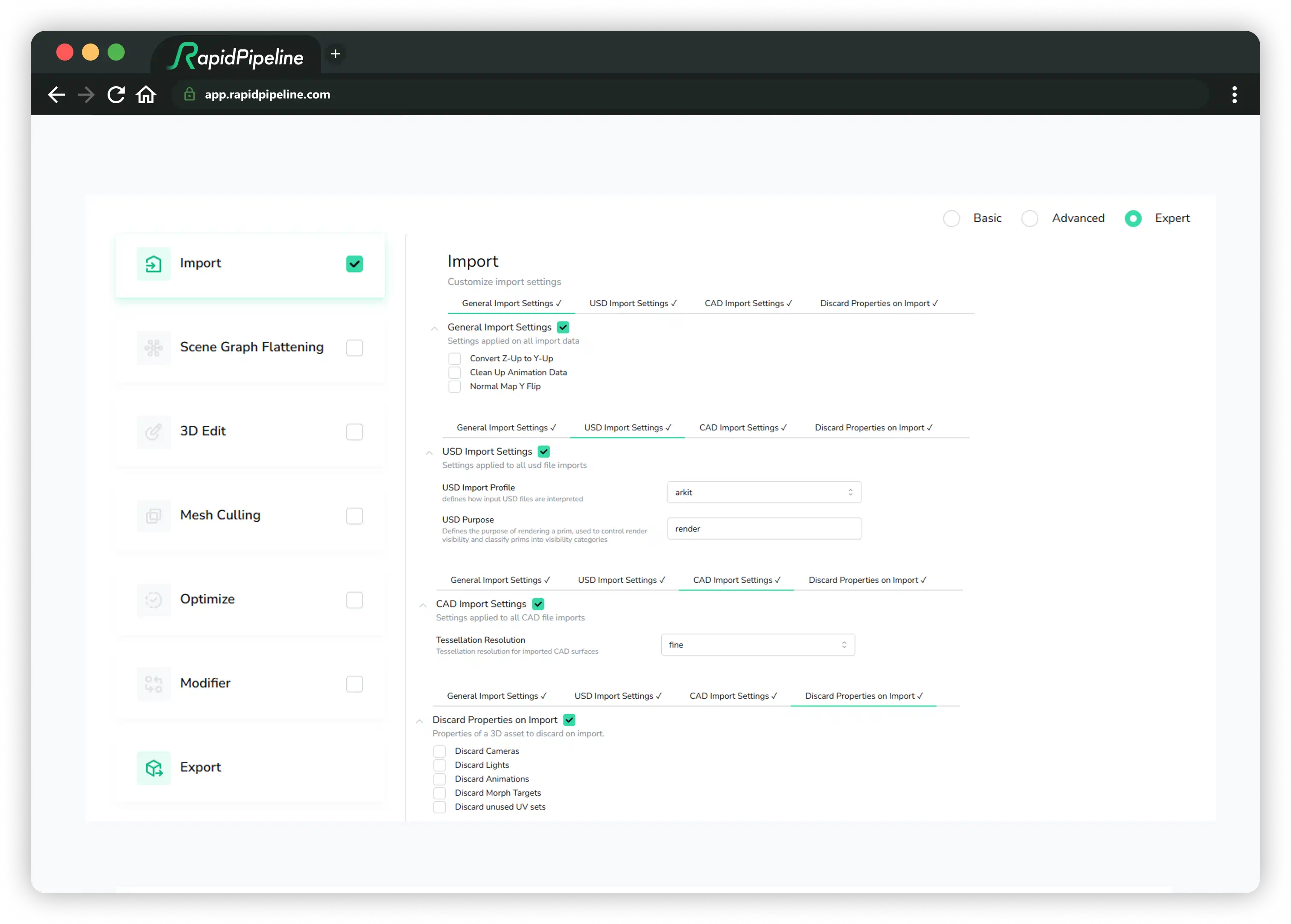
- 🗔 Web Platform UI:
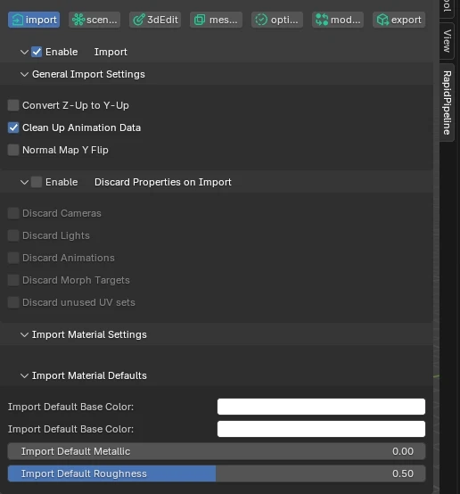
- 🔶 Blender Add-On (Expert Mode):
{
  "version": 1.4,
  "import": {
    "general": {
      "rotateZUp": false,
      "fixAnimationData": true,
      "normalmapYFlip": false
    },
    "USD": {
      "profile": "arkit",
      "purpose": "render",
      "convertDisplayColors": "never"
    },
    "CAD": {
      "tessellationResolution": "fine",
      "removeTJunctions": false,
      "sewTolerance":0.0
    },
    "discard": {
      "cameras": false,
      "lights": false,
      "animations": false,
      "morphTargets": false,
      "unusedUVs": false
    },
    "materials": {
      "undefinedDefaults": {
          "baseColor": [1,1,1,1],
          "metallic": 0,
          "roughness": 0.5
       }
    }
  },
  "export": [
    {
      "fileName": "",
      "textureMapFilePrefix": "",
      "discard": {},
      "format": {
        "gltf": {
          "pbrMaterial": {}
        }
      }
    }
  ]
}
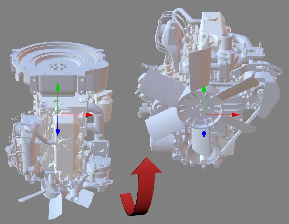
Convert Z-Up to Y-Up
Convert Z-Up to Y-Up will rotate the whole asset 90 degrees on the world X-axis.
The asset pivot can be edited with the 3D Edit function Center Object to center, rearCenter, bottomCenter, or topCenter.
Fix Animation Data
Fixes animation data by summing all skin weights for each vertex to 1.0, and assigns all weights with zero strength to bone 0.
Normal Map Y Flip
Inverts the green channel of all normal maps. If the bump maps look indented instead of out-dented, this option can help fix them. DirectX uses the Y-down convention as shown on the left, while glTF uses the Y-up convention as shown on the right.

USD Import Settings

These settings are applied to all USD file imports.
| Setting Title | Setting Name | Level | Type [Range] (Default) | Description |
|---|---|---|---|---|
| USD Profile | profile | basic | string [generic, arkit] (arkit) | Defines how input USD files are interpreted |
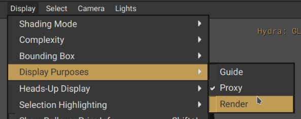
| USD Purpose | purpose | expert | string [render] (render) | Defines the purpose of rendering a prim, used to control render visibility and classify prims into visibility categories |
| Convert Display Colors | convertDisplayColors | expert | string [never, auto, vcolor, mtcolor] (never) | How to convert USD display colors |
USD Import Profile
Defines how input USD files are interpreted. There are two options:
- generic: Most USD files should use this option.
- arkit: Use this profile if a USD file was generated for use with ARKit using the Apple ARKit schema.

USD Purpose
Defines the purpose of rendering a prim, used to control render visibility and classify prims into visibility categories.
- render: This is the default string, but this can be replaced with another strong if desired.
Convert Display Colors
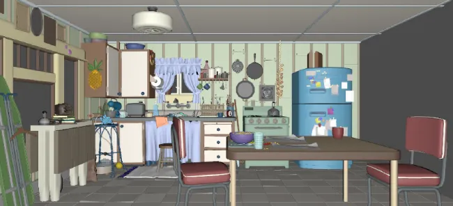
In some pipelines, USD display colors are used as lightweight lookdev lower-fidelity proxies for more complex material data; this setting controls how this data should be handled.
- never: Display colors are not converted. Display colors are preserved only if a non-optimized or non-flattened USD file is exported. This is the default setting.
- auto: Same as
vcolor. - vcolor: Tries to set display colors as vertex colors, but doesn't override existing vertex colors. If vertex colors exist already, sets display colors as material values instead. Regardless, never overwrites existing values.
- mtcolor: Sets display colors as material values.
CAD Import Settings
These settings are applied to all CAD file imports. When any of these settings are altered from the default, then the CAD file will be re-imported from the original input file and the new settings will be applied.
| Setting Title | Setting Name | Level | Type [Range] (Default) | Description |
|---|---|---|---|---|
| Resolution | tessellationResolution | basic | string [extraCoarse, coarse, medium, fine, extraFine, custom] (fine) | Tessellation resolution for imported CAD surfaces |
| CAD Remove TJunctions | removeTJunctions | expert | boolean (false) | Attempts to remove T-Junctions after CAD tessellation (experimental) |
| CAD Sewing Tolerance | sewTolerance | advanced | number [>=0 && <=1.7976931348623157e+308] (0) | Tolerance for the sewing operation on the b-reps before tessellation |
| Max Surface Deviation | maxSurfaceDeviation | expert | number [>=0 && <=1.7976931348623157e+308] (0.4) | Maximum distance between the CAD surface and the tessellation in mm (sometimes also referred to as "Chord Height") |
| Max Angle | maxAngle | expert | number [>= 10 AND <= 40] (40) | Decreasing the max angle generates more faces in high curvature areas, such as fillets for example |
| Max Edge Length | maxEdgeLength | expert | number [>= 0 && <= 1.7976931348623157e+308] (0) | Controls the maximum length of edges per face. Caution, as the value is absolute (mm), large parts might become overtessellated, including flat surfaces |
Tessellation Resolution
Imported CAD surfaces are tessellated to fine by default. Assets can be re-imported and tessellated to other target resolutions if desired.
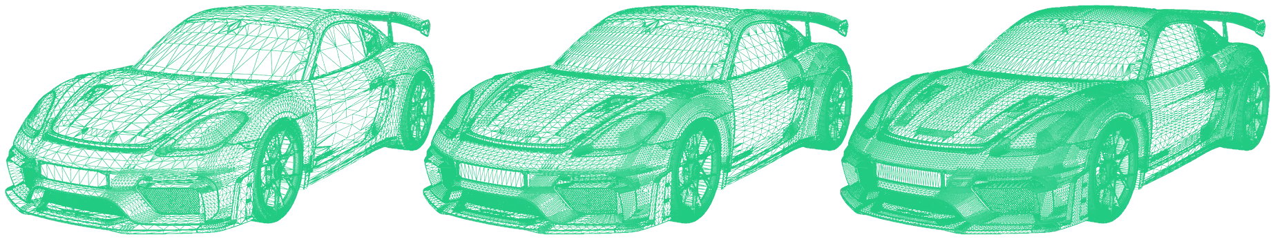 from left to right:
 coarse, medium, fine resolution
Choose resolution custom in order to steer the tessellation process with one of the following expert settings:
Dive deeper into Tessellation Settings within the 3D Processor CLI CAD Tessellation Tutorial.
Please also refer to our public CAD Dataprep repository.
It covers multiple CAD data preparation workflows on representative publicly available sample CAD data sets.
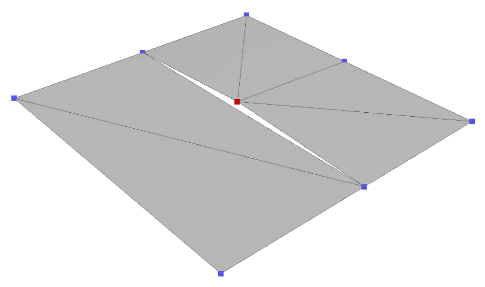
CAD Remove T-Junctions
This setting attempts to remove T-junctions after tessellation has been completed. This is currently an experimental feature.
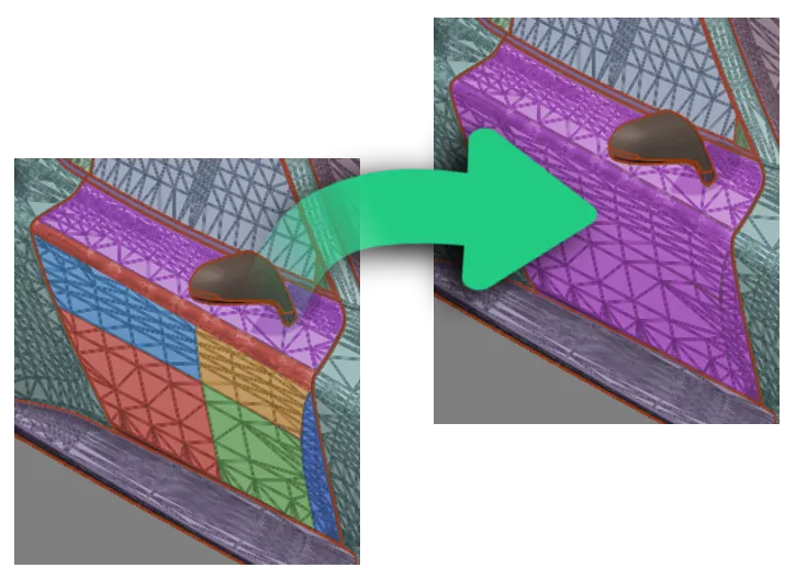
CAD Sewing Tolerance
Tolerance for the sewing operation. The sewing process is directly performed on the b-reps or boundary representations before any tessellation takes place.
This helps merge multiple surface parts into coherent mesh parts.
The values are in mm. Minimum is 0 , maximum 1,000,000,000,000.
A setting of 0 will disable the function.
We recommended a value of 0.05 mm, which means that surfaces with a gap greater than 0.05 mm will not be welded together.
This value is also the default within the CAD Import Action of the RapidPipeline Integrations.
Expert Tessellation Settings
These settings require tessellationResolution to be set to custom.
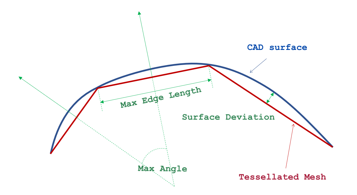
Max Surface Deviation
Maximum distance between the CAD surface and the tessellation in mm (sometimes also referred to as "Chord Height").
The lower this value the closer the tessellated mesh surface will be compared to the original CAD surface - this usually also translates to a much denser mesh resolution and thus a heavier file.
Max Angle
Decreasing the max angle generates more faces in high curvature areas, such as fillets, soft bevels or round corners for example.
Max Edge Length
Controls the maximum length of edges per face.
As the maxEdgeLength value is absolute (mm), large parts might become overtessellated, including flat surfaces and even if the maxSurfaceDeviation and maxAngle settings are set very high (= low mesh resolution).
Discard Properties on Import
Properties of the 3D assets can be discarded on import.
| Setting Title | Setting Name | Level | Type [Range] (Default) | Description |
|---|---|---|---|---|
| Discard Cameras | cameras | basic | boolean (false) | if true, discards any imported cameras |
| Discard Lights | lights | basic | boolean (false) | if true, discards any imported lights |
| Discard Animations | animations | basic | boolean (false) | if true, discards any imported animations |
| Discard Morph Targets | morphTargets | advanced | boolean (false) | if true, discards any imported morph targets (shape keys, blend shapes) |
| Discard unused UVs | unusedUVs | expert | boolean (false) | "if true, discards unused UV sets (if possible) |
Discard Cameras
All cameras will be removed from the 3D assets.
Discard Lights
All lights will be removed from the 3D assets.
Discard Animations
All animations will be removed from the 3D assets. Assets will show the state at frame zero.
Discard Morph Targets
All morph targets will be removed from the 3D assets.
Discard unused UV sets
All texture coordinates which are not referenced by any textures will be removed from the 3D assets.
Import Material Settings
Settings for the directly imported Materials from the source data set(s).
| Setting Title | Setting Name | Level | Type [Range] (Default) | Description |
|---|---|---|---|---|
| Import Default Base Color | baseColor | basic | array [>= 4 && <= 4] ([1,1,1,1]) | default base color values, applied on import if the material model doesn't define a default base color values already |
| Import Default Metallic | metallic | basic | number [>= 0 && <= 1] (0) | default metallic value, applied on import if the material model doesn't define a default metallic value already |
| Import Default Roughness | roughness | basic | number [>= 0 && <= 1] (0.5) | default roughness value, applied on import if the material model doesn't define a default roughness value already |
Import Material Defaults
Materials can be assigned default properties, which are applied on import if the material model doesn't define default properties already.
Import Default Base Color
Materials can be assigned a default base color.
Note this color has four components: red, green, blue, and alpha.
Import Default Metallic
Materials can be assigned a default metallic value.
Minimum 0, maximum 1, default 0.
Import Default Roughness
Materials can be assigned a default roughness value.
Minimum 0, maximum 1, default 0.5.
Further Documentation
For the full Documentation on all available data operations commands and system settings, please refer to the CLI Commands Guide and 3D Processor System Schema & Settings.
The 3D Processor is available for multiple interfaces: