
Schemas & Settings

Schemas

Introduction

RapidPipeline 3D Processor schemas are a set of rules that represent and validate the structure and format of RapidPipeline's 3D processing functionalities.

RapidPipeline maintains this semantic normalization by using schemas. Schemas are the standard way of describing data processes in RapidPipeline, allowing all data that conforms to schemas to be reused across all different tools and interfaces without conflicts.

note

In addition to describing the structure of data, schemas apply constraints and expectations to data so it can be validated as it moves between systems. These standard definitions allow data to be interpreted consistently, regardless of origin, and remove the need for translation across applications.

Available Versions and Compatibility

The 3D Processing Schemas are utilized by multiple RapidPipeline Software Packages & Interfaces as validation for JSON Settings files . Generally the most recent schema version will be adopted and applied within all interfaces.

caution

Newer 3D Processing Schemas are only compatible with the corresponding newer 3D Processor CLI versions. Settings created against the newer schemas might not validate with older versions of the 3D Processor! See the corresponding schemas and software releases below.

Web Platform

The RapidPipeline Platform and API are usually always on the latest Schema version.

3D Processor CLI

CLI Version3D Processing Schema & Settings (link)Description
v7.4.03D Processing Schema v1.4Direct operations on the 3D Data, such as Optimization, Compression, etc.
v7.3.03D Processing Schema v1.3Direct operations on the 3D Data, such as Optimization, Compression, etc.
v7.2.03D Processing Schema v1.2Direct operations on the 3D Data, such as Optimization, Compression, etc.
v7.1.0 - v7.1.13D Processing Schema v1.1Direct operations on the 3D Data, such as Optimization, Compression, etc.
v7.0.03D Processing Schema v1.0Direct operations on the 3D Data, such as Optimization, Compression, etc.

Integrations

Integration & Version3D Processing Schema & Settings (link)Remarks
Blender Add-On v0.2.43D Processing Schema v1.4Supports RapidPipeline Actions, 3D Processor Settings are now presented as Expert Mode
Blender Add-On v0.2.33D Processing Schema v1.3First experimental version of RapidPipeline Actions. Uses 3D Processing Settings validated against v1.3 schema.
Blender Add-On v0.2.23D Processing Schema v1.2Uses 3D Processing Settings validated against v1.2 schema.
Blender Add-On v0.2.13D Processing Schema v1.1Uses 3D Processing Settings validated against v1.1 schema.
Blender Add-On v0.2.03D Processing Schema v1.0Uses 3D Processing Settings validated against v1.0 schema.

Settings

RapidPipeline 3D Processing Configuration Settings adhere to the 3D Processing Schema and are designed to achieve any 3D processing goal. They are operating directly on a 3D model and are able to alter the entire structure or re-create meshes, materials, UVs, texture maps and other 3D model properties.

info

See here for a more exhaustive list of all availabe settings and how they relate to the 3D Processing Schema.

Data Categories and Types

Data within the 3D Processing Settings JSON Files can be divide into 3 high-level categories :

Setting

Settings Group

Operation

note

Categories and states are high-level concepts and serve only documentation purposes. They can not be found within the 3D Processor Schema or defined within the JSON Settings files themselves.

Each Category has a specific Type and an optional State:

  • Types: Define the kind of data type for any value in JSON.

    • object, string, boolean, number, array
  • State: Define special behavior and usage within the settings JSON for any value.

    • toggle = this state indicates that a setting, group or operation has to be specified ("toggled") in order to have any effect.
info

Settings, settings groups or operations without the toggle state, have always a default behavior, either directly or via children, no matter if they are specified or not (= omitted). For example if the import object is not specified, imported CAD data is still tessellated via the CAD settings group child object and it's tessellationResolution setting using the default resolution fine.


oneOf choices

In addition within the 3D Processor Settings Documentation oneOf choices are indicated by the following tag:

oneOfChoice

tip

Properties with the oneOfChoice tag indicate that the respective choice has to be specified within the configuration to have an effect and multiple oneOf tagged properties within the same parent object are not allowed.


Associations between the categories:

Setting

  • possible types: string, boolean, number, array
  • possible states: toggle

Settings can be of any available type other than object and can sometimes be of state toggle. Settings can not hold any nested data, as they are no objects.


Settings Group

  • possible types: object
  • possible states: toggle

Settings Groups are always of type object and can be of state toggle. Settings Groups can hold different nested data, such as Settings, other Settings Groups or even Operations.


Operation

  • possible types: object, array
  • possible states: toggle

Operations are usually of type object and mostly of state toggle. Operations are similar to Settings Groups but trigger active functionality within the 3D Processor.


Examples:

import Settings Group type : object

export Operation type : array state: toggle

info

Even though the export operation is of state toggle it is also required as per 3D Processor Schema. That means that within one settings file the export object does not have to be specified as long as another configuration holds that property or an --export command (from CLI v7.2.0 on) is utilized.

Presets

A set of 3D processing configuration settings in the RapidPipeline Web Platform is described as a 3D Processor Preset.

In order to try out some example presets the new 3D Processor Presets in the RapidPipeline Web Platform can be utilized.

note

See the update regarding the new presets in the Product Updates section here

To download a preset in editable JSON format, activate Preview New Settings with the radio button and download the respective settings JSON files via the Actions menu:

Example banner

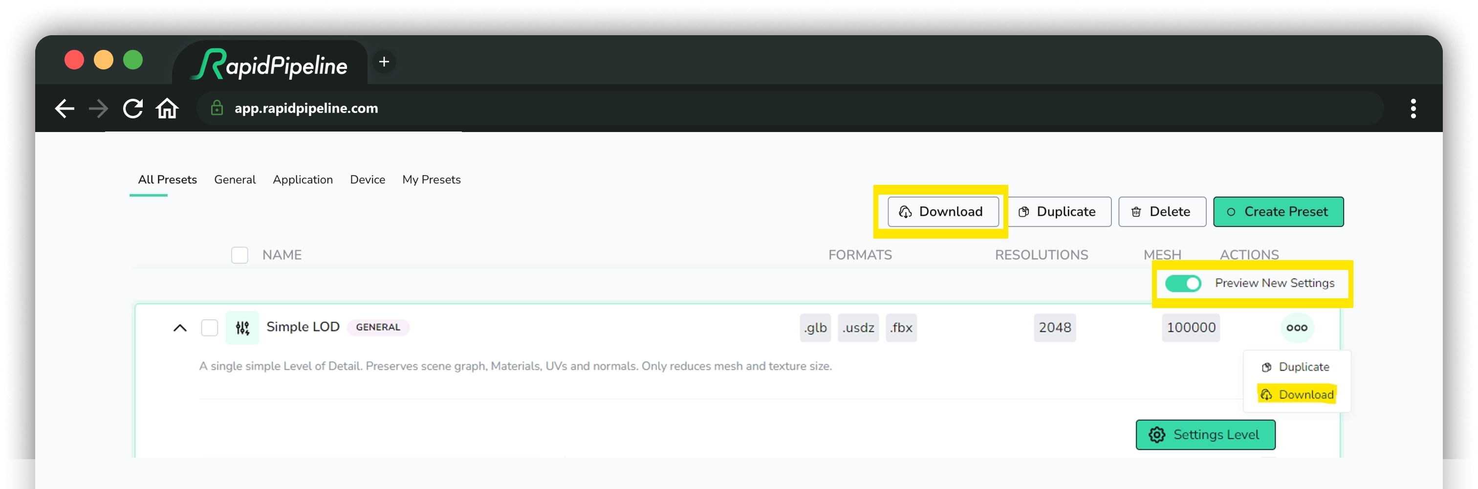
These JSON settings files can be ingested by the RapidPipeline Blender Add-On or the RapidPipeline 3D Processor CLI.

tip

Learn more about how to ingest the JSON settings files with the 3D Processor CLI here: https://docs.rapidpipeline.com/docs/componentDocs/3dProcessor/cli-setup-guide#command-line-examples

Settings Guide

RapidPipeline 3D Processor logo

Import

These settings are applied by RapidPipeline 3D Processor to assets on import.

General Import Settings

These settings are applied to all input data, regardless of file format.

Convert Z-Up to Y-Up

Convert Z-Up to Y-Up will rotate the whole asset 90 degrees on the world X-axis.

tip

The asset pivot can be edited with the 3D Edit function Center Object to center, rearCenter, bottomCenter, or topCenter.

Engine asset is shown before and after rotation, with red 3D arrow

Clean Up Animation Data

Fixes animation data by summing all skin weights for each vertex to 1.0, and assigns all weights with zero strength to bone 0.

Normal Map Y Flip

Inverts the green channel of all normal maps. If the bump maps look indented instead of out-dented, this option can help fix them. DirectX uses the Y-down convention as shown on the left, while glTF uses the Y-up convention as shown on the right.

A normal map of a sphere is shown before and after flipping the green channel

USD Import Settings

These settings are applied to all USD file imports.

USD Import Profile

Defines how input USD files are interpreted. There are two options: generic and arkit.

USD Purpose

Defines the purpose of rendering a prim, used to control render visibility and classify prims into visibility categories. The default string is render, but this can be replaced with another string as needed.

CAD Import Settings

These settings are applied to all CAD file imports. When any of these settings are altered from the default, then the CAD file will be re-imported from the original input file and the new settings will be applied.

Tessellation Resolution

Imported CAD surfaces are tessellated to fine by default. Assets can be re-imported and tessellated to medium or coarse resolution if desired.

A car asset with three different resolutions shown

CAD Remove T-Junctions

This setting attempts to remove T-junctions after tessellation has been completed. This is currently an experimental feature.

CAD Sewing Tolerance

Tolerance for the sewing operation on the b-reps before tessellation.

Minimum 0, maximum 1,000,000,000,000.

A setting of 0 will disable the function.

Discard Properties on Import

Properties of the 3D assets can be discarded on import.

Discard Cameras

All cameras will be removed from the 3D assets.

Discard Lights

All lights will be removed from the 3D assets.

Discard Animations

All animations will be removed from the 3D assets. Assets will show the state at frame zero.

Discard Morph Targets

All morph targets will be removed from the 3D assets.

Discard unused UV sets

All texture coordinates which are not referenced by any textures will be removed from the 3D assets.

Import Material Settings

Import Material Defaults

Materials can be assigned default properties, which are applied on import if the material model doesn't define default properties already.

Import Default Base Color

Materials can be assigned a default base color.

Note this color has four components: red, green, blue, and alpha.

Import Default Metallic

Materials can be assigned a default metallic value.

Minimum 0, maximum 1, default 0.

Import Default Roughness

Materials can be assigned a default roughness value.

Minimum 0, maximum 1, default 0.5.

3D Edit

RapidPipeline 3D Processor has advanced tools for manipulating the shading of 3D meshes. Smooth/hard edges can be modified, UVs can be generated, new materials can be assigned, assets can be re-centered, and more.

Mesh Normals

Mesh normals control the shading of meshes. There are two controls here: the Normal Hard Angle Threshold, and the Normal Computation Method.

These two controls work independently from each other... the Threshold controls which edges are marked "hard", while the Method affects the directions of the "soft" normals.

Normal Hard Angle Threshold

The threshold is specified in degrees and is used for splitting vertex normals, which controls which edges should be changed into soft or hard. This is an easy way to break up blobby shading, by adding sharp edges.

Lamp model with three different thresholds
Normal Hard Angle Threshold at 0 degrees, 60 degrees, and 180 degrees.

  • 0 = All edges become sharp. This is essentially flat shading.
  • 60 = The model will get hard edges where ever neighboring faces are angled more than 60 degrees from each other. This is the default value.
  • 180 = All edges become soft.

Normal Computation Method

The method affects how the angles of the normals for soft edges are handled.

Lamp model with two different methods
Normal Computation Methods: Angle (left) and Area.

  • Angle: The angles of normals are averaged across all edges. This works well for most surfaces, including organic models.
  • Area: This weights the normals more towards the larger faces. This works especially well when a model has bevels or fillets. This method is sometimes called "face-weighted normals".

Model Edit

These settings are applied just before Export. Changes made here do not affect other processing methods, for example any operations which rely on units or the size of the bounding box are done using the transform matrix of the incoming assets.

Scaling Factor

Assets can be scaled before Export. A value of 1.0 means no change is applied.

Center Object

Assets can be re-centered before Export.

  • Center = The asset is centered on the world origin.
  • Rear Center = The rear center of the asset is placed at the world origin.
  • Bottom Center = The bottom center of the asset is placed at the world origin.
  • Top Center = The top center of the asset is placed at the world origin.

Material Edit

Materials and UVs can be replaced, optimized, or refined.

Alpha Conversion

Materials using transparency can be converted to opaque, or to use alpha mask instead of blend.

These conversions are particularly helpful for assets produced with Clo3D or Browzwear, which use alpha blend for mesh fabrics and decals.

Alpha blend often causes sorting errors in real-time renderers, where far surfaces are rendered in front of near surfaces. Alpha mask avoids these issues, at the expense of allowing only on/off transparency.

Converting alpha blend to opaque can also be useful, when textures are using alpha channels that contain only white pixels. In this case, alpha blending is superfluous and can be disabled entirely.

A threshold can help preserve transparency for surfaces that may benefit from keeping a low amount of blend, for example semi-transparent glass or plastic.

  • Alpha Blend to Mask Conversion = Change the material to alpha mask if the alpha blend seems to be using mostly high contrast values. Conversion becomes more aggressive as the threshold is decreased. 1.0 changes no materials, 0.0 changes all materials to alpha mask.
  • Alpha to Opaque Conversion = Change the material to opaque if the alpha seems to be opaque; i.e. mostly white. Conversion becomes more aggressive as the threshold is decreased. 1.0 changes no materials, 0.0 changes all materials to opaque.

Material Replacer

Allows for replacing materials with default materials or replacing texture maps with values. This can help if an asset has no materials, or materials have been inconsistently applied.

Default Material

New basic PBR materials can be generated for all surfaces.

  • Base Color = A new base color can be specified. This can include an alpha value, however alpha is not enabled for the resulting material. Alpha blending should be applied judiciously as it often causes sorting errors in real-time renderers.
  • Metallic = A new metallic value can be specified. In PBR material models, metallic is best at either 1.0 or 0.0 since in-between values tend to cause unpredictable non-physical behavior.
  • Roughness = A new roughness value can be specified. Roughness is an approximation of micro-surface facets, with zero being completely glossy and 1 being completely rough.
Generate UVs

New UVs can be generated for all meshes in the asset. These UVs replace any existing texture coordinates, and are stored in UV0.

Cube Unwrapping

New UVs are generated using three planar projections.

The scale of the projections can be adjusted: 1.0 means the UV will be 1 meter square. As the scale is increased, the UVs will tile more, and the texture will appear smaller. Decreasing the scale causes the texture to appear larger.

  • To apply Real-World Scale of 1 unit = 1 centimeter, use 100, which is how many centimeters there are in a meter.
  • To apply Real-World Scale of 1 unit = 1 inch, use 39.37, which is how many inches there are in a meter.

A 1-meter box and sphere with three different cube unwrap scales
A 1-meter box and sphere showing Cube Unwrap Scale: 1 (left), 4, and 0.25.

Add Checker Texture

This will add a 1024x1024 JPG checker texture into the Base Color input of the material.

The checker texture
The 1024x1024 checker texture.

A 1-meter box and sphere without the checker texture, and with
A 1-meter box and sphere without the checker texture (left), and with the checker texture at Cube Unwrap Scale 0.25.

Drop Uniform Texture Maps

Flat-color or nearly-flat-color textures can be automatically culled from materials, and a number for the average value will be used instead. This can dramatically reduce file sizes and draw calls.

A threshold can be used to influence how "empty" a texture needs to be before it is culled.

  • Zero disables culling; set the threshold more than zero to enable culling.
  • A threshold of 0.01 means there must be no more than 1% difference between all pixels for a texture to be culled.
  • A threshold of 1 means all pixels in the texture may have 100% difference and they will still be culled, so all textures are removed regardless of how much texture information is present.

To apply culling to all textures, increase the Default Texture Map Threshold to be more than zero.

To apply culling only to specific texture inputs, increase the threshold for specific texture types.

Repair

Vertex Merging

Merges close vertices with a given threshold.

Vertex Merging Per Mesh decides if vertex merging should only be performed within each mesh node (on) or across all nodes (off).

There are two choices for controlling the merging distance:

  1. Vertex Merging Distance Percentage - Percentage distance for vertex merging.
  2. Vertex Merging Distance Value - Value in scene units for vertex merging.

Fix Winding Order

Automatically flip the winding order of triangles or parts (mesh lumps) according to certain metrics.

There are two choices for controlling the visibility calculation:

  1. Visibility Mode: default
  2. Visibility Mode: mesh

Scene Graph Flattening

The scene graph is a list of all the nodes in the asset, including meshes, cameras, lights, materials, etc. These nodes may be linked in a hierarchy, with parent-child relationships that affect their inherited transforms.

RapidPipeline 3D Processor's Scene Graph Flattening only applies to mesh nodes. Four unique flattening modes allow the graph to be intelligently simplified by combining and splitting nodes based on shared properties.

Reducing the number of mesh nodes can help improve performance (primarily by reducing draw calls), but can also improve decimation and other actions by allowing multiple surfaces to be treated together during processing.

info

Some formats (e.g. OBJ) do not support hierarchies or instances. For these formats, our exporters do their best to at least keep individual meshes.

Flattening Method

Several methods are provided for controlling how nodes are combined.

None

No flattening will be applied, the scene graph will remain the same as in the input. This mode produces the highest number of draw calls, but it preserves all nodes and any instancing if present.

Full

All meshes will be combined into a single mesh, using a single material. If the input meshes use different materials, the properties and textures will all be combined into a single shared material.

By Opacity

Meshes all non-transparent meshes together into a single mesh, and keeps all the transparent meshes separate. Transparent meshes are not combined together, because often this improves depth sorting in real-time rendering.

By Material

Meshes using the same material will be combined together. This can change the number of meshes, but will keep the same number of materials as the input.

Auto

Let RapidPipeline 3D Processor decide. At the moment, this is the same as using By Opacity.

Material Merging

Material merging is automatically handled when nodes are flattened, depending on the mode. By Opacity, Auto and Full will automatically merge materials as needed.

Benefits and Drawbacks of Not Flattening

Not using any flattening has specific benefits and potential downsides, depending on what mode is chosen for the specific input mesh.

Benefits:

  • Individual nodes and subtrees can continue to be selected and processed within your optimized model.

  • If the input contains instances of meshes, they can be maintained as instances and stored/rendered efficiently. Flattening tends to remove instancing.

  • If the input contains transparent meshes, the renderer will likely be able to render them in the correct order, even after optimization.

Potential Downsides:

  • More complex files, and possibly larger file sizes.

  • More draw calls, leading to reduced rendering performance if the model has large numbers of nodes and meshes.

  • Some operations like decimation may behave in unexpected ways, e.g. create cracks between unconnected but aligned meshes. Flattening meshes before decimation can help prevent this.

Two closeups of the chair arm
Merging meshes together will help prevent gaps from appearing between them when they are optimized. Scene Graph Flattening byMaterial (left), versus None (right). See Tutorial: CLI Preserve UVs for a step-by-step tutorial.

Flattening Examples

FlightHelmet flattening methods compared
Flattening applied to the model FlightHelmet.glTF. Top-left: flattened "byOpacity"/"auto"; Top-right: flattened "none"; Bottom-left: flattened "full"; Bottom-right: original.

When comparing modes, each output has a different number of draw calls and nodes:

  • Flattening mode "full" in the bottom left corner lost the transparency because full disregards transparency. This can be particularly useful for distant LODs (level of detail models).

  • Flattening mode "byOpacity" produces two draw calls from two different meshes so that the transparent glasses and the opaque parts can be rendered correctly. If the opaque parts used alpha, most real-time renderers would cause noticeable sorting errors, thus it's usually best to keep them separate.

  • Flattening mode "none" has almost the same result due to the structure of the input mesh. Note this will differ depending on the organization of the input mesh and hierarchy.

  • Flattening mode "auto" produces results supporting and preserving transparency without compromising the performance too much. An input file with a lot of unique transparent parts will have more draw calls than with the full flattening mode, but the consequences regarding performance are often still minor. Usually the benefits of preserving transparency should outweigh the additional draw calls and nodes.

FlightHelmet flattening hierarchies compared
From left to right: "full", "byOpacity"/"auto", "byMaterial, "none", and the original input.

The hierarchies of the generated results give a good overview on how RapidPipeline can use a grade of flattening specifically tailored to the needs of each final application.

The flattening mode "none" will preserve the nodes and naming conventions of the original, whereas "full" and "byOpactiy" modes will flatten either everything or all opaque nodes, respectively.

The "byMaterial" mode will usually produce a different number of nodes than given in the input model. The only difference between "byMaterial" and "byOpacity" is that the latter will merge together all nodes that have the same opacity category (transparent or opaque), while "byMaterial" merges together all nodes that have the same material.

The flattening mode "none" will preserve Material IDs. However if the input materials are using textures on one or multiple atlases, RapidPipeline will always re-bake all materials on a number of atlases defined by the given atlas mode setting.

To simplify the model but also preserve all original texture maps and UV coordinates, in the Decimator choose the option Keep Materials and UVs. This will preserve tiled textures, and optionally add a 2nd UV channel for non-tiled ambient occlusion.

Preserved Scene Depth Level

This number acts as an overall limit, preserving a minimum number of scene graph levels, by allowing some nodes to be combined while preserving others based on their level in the hierarchy.

Zero is the default, meaning no limits will be applied, so the flattening of the scene graph will be fully controlled by the flattening mode. Increasing the Preserved Scene Depth Level will increase the number of levels to be preserved.

Preservation Examples

MosquitoInAmber scene graph
The input scene graph for MosquitoInAmber.glb.

MosquitoInAmber scene graph
After processing with flattening mode byOpacity, and increasing the preservation level, sceneDepth 1 and 5 have a very distinguishable effect on the scene graph. Note that material names are not preserved, as these might tend to be merged depending on opacity.

MosquitoInAmber scene graph
If the same levels are used with flattening mode byMaterial, this will preserve all materials and their names.

Further Documentation

For the full Documentation on all available data operations commands and system settings, please refer to the CLI Commands Guide and 3D Processor System Schema & Settings.