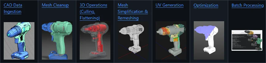
Tutorial: 3D Processor CAD Tessellation
| This tutorial contains these key points: |
|---|
| ✔️ Introduction - CAD Processing |
| ✔️ CAD Import and Settings |
| ✔️ Example CAD Asset |
| ✔️ CAD Import & Tessellation |
This tutorial shows how to use RapidPipeline 3D Processor CLI to import and tessellate a CAD data set. The tutorial requires basic knowledge on how to create and use a Settings Preset Config file, and how to utilize the RapidPipeline 3D Processor CLI.
If you are just starting out with the RapidPipeline 3D Processor CLI please refer to the introductory tutorial first. RapidPipeline 3D Processor is a powerful 3D data optimization and automation toolset; for more information please see the product overview.
RapidPipeline CAD Data Preparation Samples
GitHub: RapidPipeline-CAD-Data-Preparation-Samples is a collection of CAD data preparation & 3D processing workflows using publicly available sample assets.
We've included settings recipes for RapidPipeline 3D Processor CLI to illustrate what is needed for an optimal conversion from parametric CAD data into tessellated meshes suitable for CGI and real-time visualization use-cases.
Introduction - CAD Processing
In order to start working with CAD (Computer-aided design) data within a polygon (mesh) based 3D Modeling Software, the CAD model or solid has to be converted into a polygonal representation first. This conversion process is called tessellation.
A solid usually consists of B-reps or boundary representations which are based on NURBS (Non-Uniform Rational B-Splines) surfaces. These surfaces usually come in form of patches which also need to be considered within the tessellation process.
Within this tutorial we will utilize the RapidPipeline CAD Import and Tessellation Settings in order to control this process and prepare the model for additional (mesh) modeling or optimization (e.g. mesh simplification) steps.
CAD Import and Settings - Overview
CAD Import Settings are applied directly on the b-rep data instead of any mesh conversion. This is the main differentiator between them and other 3D Processing settings which are always operating on a tessellated ingested data-set (mesh).
Configuration Example
- 🖹 In the JSON Settings File:
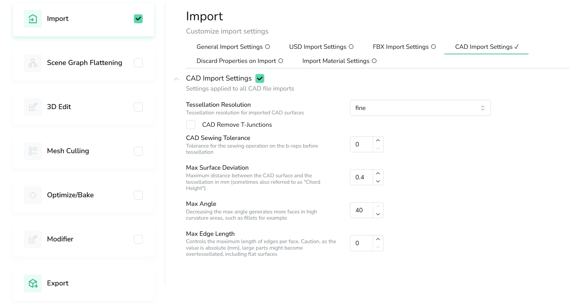
- 🗔 In the Web Platform UI:
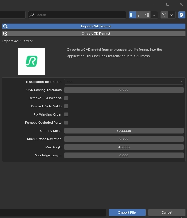
- 🔶 In the Blender Add-On (Action):
{
  "version": 1.5,
  "import": {
    "CAD": {
      "tessellationResolution": "fine",
      "removeTJunctions": false,
      "sewTolerance":0.0,
      "maxSurfaceDeviation":0.4,
      "maxAngle":40,
      "maxEdgeLength":0
    }
  },
  "export": [
    {
      "fileName": "",
      "textureMapFilePrefix": "",
      "discard": {},
      "format": {
        "gltf": {
          "pbrMaterial": {}
        }
      }
    }
  ]
}
CAD Settings covered within this Tutorial
tessellationResolutionmaxSurfaceDeviationmaxAnglemaxEdgeLength
The following Settings are not covered within this Tutorial:
removeTJunctionssewTolerance
Learn more about all CAD Import Settings within our 3D Processing Settings Guide
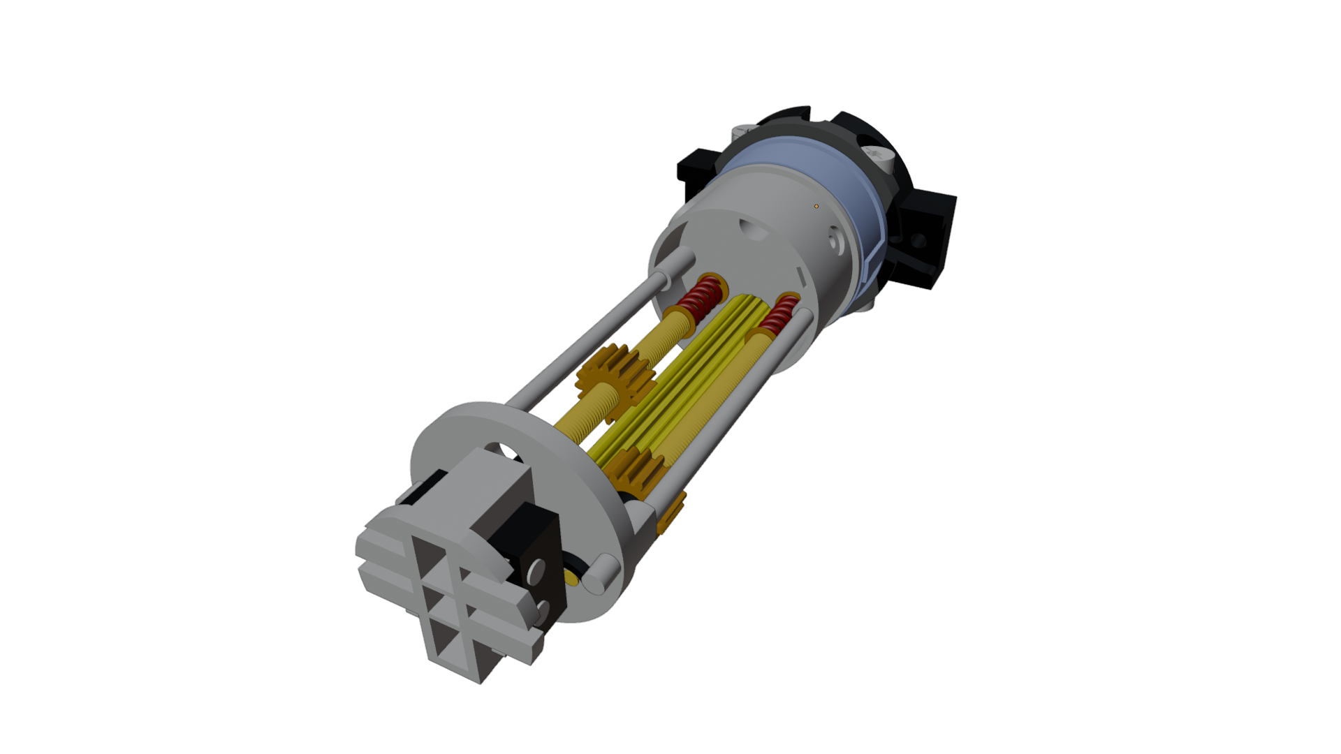
Example CAD Asset
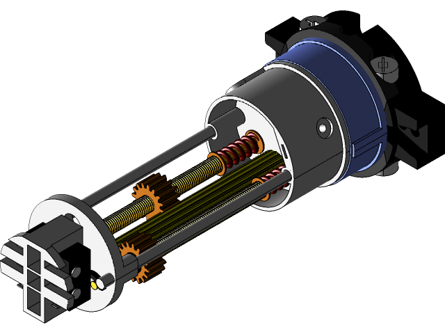
Input data - representation of breps before tessellation - cc0 public domain CAD model by Paul Buttefly
Properties of the Example CAD Model
Even though the example model is quite simple structure-wise it depicts a few different challenges for any tessellation process:
- Flat hard-surface solids (e.g. primitives) with mostly perpendicular normal directions combined with curved surface elements
- Curved surfaces in various complexities (from cylindric shaped solids to helices).
- Holes and other substraction operations (e.g. boolean operations)
The following additional CAD properties are not covered here and will be examined in an additional tutorial:
- Fillets
- Patches
- CAD patches can be merged propperly on import and before tessellation using the
sewTolerancesetting. Learn more about it here
- CAD patches can be merged propperly on import and before tessellation using the
- Complex curved surfaces such as Sadle Surfaces
Performing a CAD Import and Tessellation
We will now use the 3D Processor CLI to import and tessellated this example CAD data set, starting with a simple default configuration.
We will cover the following setting:
tessellationResolutionextraCoarse,coarse,medium,fine,extraFine
These 5 options are tessellation presets and work on a ratio based heuristic offering different density levels of the tessellation. The custom option works different and will be explained in the next section further below.
| Steps: |
|---|
| 1. Download the CAD file: start-stop shutter mechanic.step) |
2. Create a new text file in the same folder as a 3D asset, named importCAD.json. This will be the Config file. |
| 3. Copy the sample JSON settings code from the CAD Import Setting section and paste it into the new file. |
4. Make sure the file ending is actually json (e.g. not json.text) and hit yes if prompted when renaming the file format ending. Save the edited Config file. |
5. On windows, in the same folder containing the 3D model and the Config, open PowerShell. This can be done by holding the Shift key, right-clicking in the folder, and choosing Open PowerShell window here. |
| 6. Type (or copy-paste) the CLI command below, and press the Enter key. |
rpdx -i 'start-stop shutter mechanic.step' --read_config importCAD.json -r -o output
In windows Powershell or any other Commandline you can usually hit tab to find files within the local directory. In addition when doing that the ' will automatically be wrapped around file names containing breaks.
The commandline output should then look like this:
Validated configuration file.
Unlocked via RapidPipeline account.
Loading asset from file "start-stop shutter mechanic.step".
Skipping optimize
Saving asset to file "output\0_gltf\start-stop shutter mechanic.gltf".
Directory output\0_gltf does not exist, will be created.
Initial Results
All images shown are taken within Blender. All CAD operations are also available within the RapidPipeline Integrations via the CAD Import Action.
Tessellated result with default settings
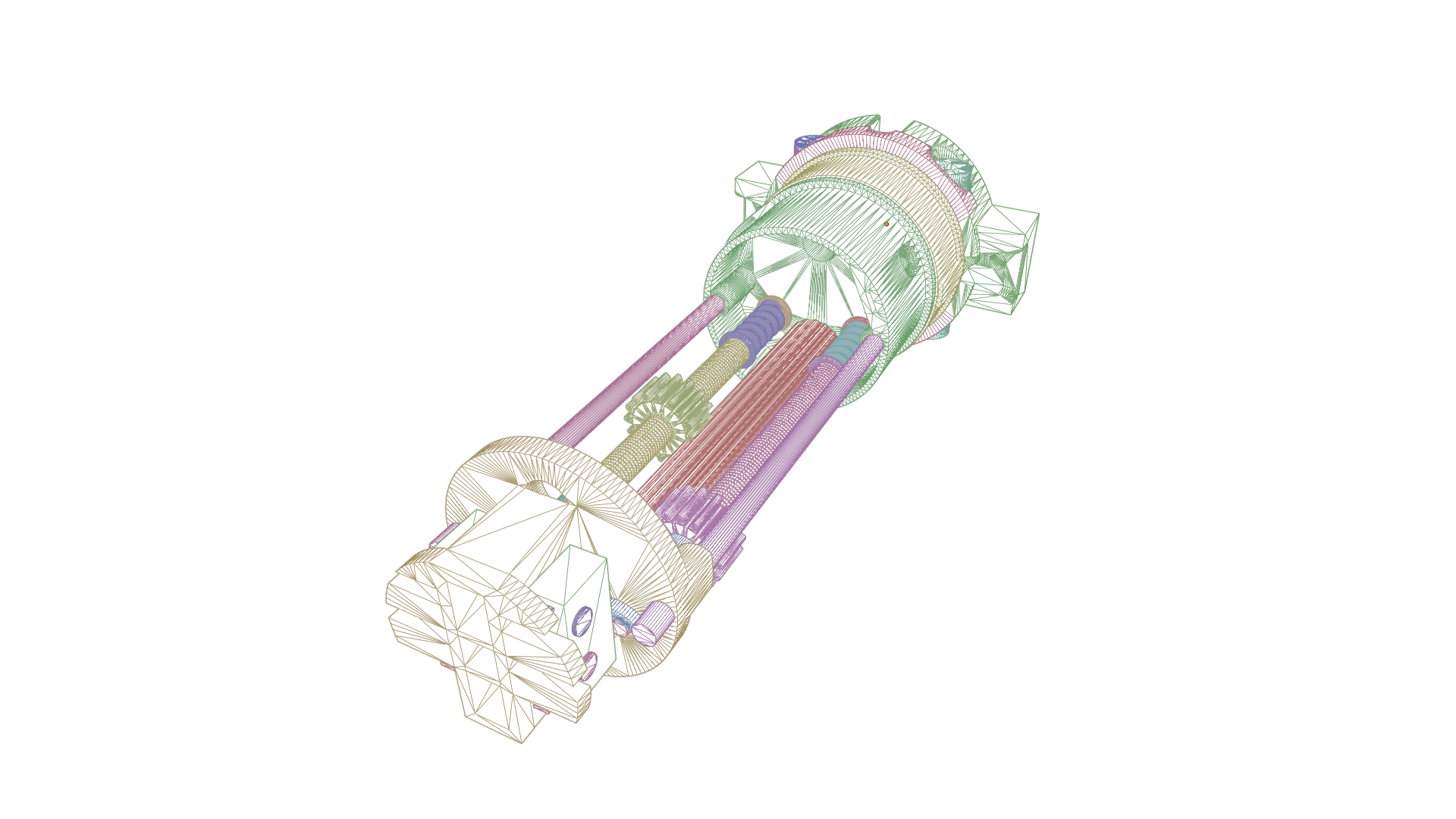
Tessellated result with default settings - wireframe view
As you can see, the default tessellationResolution fine was utilized to convert the b-reps of the input CAD data set into a polygon mesh.
The fine resolution results in a quite dense distributon of triangles and also attributes more triangles to smaller and detailed areas of the original solids.
This is a great start with a good representation of the original CAD data, especially if we do not necessary want to continue editing the mesh by hand. However, we might want to try something else as well in order to have a bit more control over the tessellation process itself.
Tweaking CAD Import Settings
In this section we will utilize another option for tessellationResolution which is custom.
This will essentially disable all the tessellation presets and activates the following expert tessellation settings:
    - `maxSurfaceDeviation`
    - `maxAngle`
    - `maxEdgeLength`
The expert tessellation settings maxAngle, maxSurfaceDeviation and maxEdgeLength require tessellationResolution to be set to custom. Learn more about the expert tessellation settings here.
Max Surface Deviation
Maximum distance between the CAD surface and the tessellation in mm (sometimes also referred to as "Chord Height").
The lower this value the closer the tessellated mesh surface will be compared to the original CAD surface - this usually also translates to a much denser mesh resolution and thus a heavier file.
Max Angle
Decreasing the max angle generates more faces in high curvature areas, such as fillets, soft bevels or round corners for example.
Max Edge Length
Controls the maximum length of edges per face.
For this tutorial we will focus on the maxSurfaceDeviation, as maxEdgeLength and maxAngle are already fine as defaults.
Within the steps below we will adjust the maxSurfaceDeviation to a value of 0.2 mm. This means that the deviation between original CAD surface and tessellated mesh will be not larger than 0.2 mm.
| Steps: |
|---|
1. Copy the sample JSON settings file and rename it to importCADcustom. |
2. Within the importCADcustom JSON config adjust the following settings: |
      "tessellationResolution": "custom",
      "maxSurfaceDeviation":0.2,
      "maxAngle":40,
      "maxEdgeLength":0
3. Make sure the file ending is actually json (e.g. not json.text) and hit yes if prompted when renaming the file format ending. Save the edited Config file. |
4. On windows, in the same folder containing the 3D model and the Config, open PowerShell. This can be done by holding the Shift key, right-clicking in the folder, and choosing Open PowerShell window here. |
| 5. Type (or copy-paste) the CLI command below, and press the Enter key. |
rpdx -i 'start-stop shutter mechanic.step' --read_config importCADcustom.json -r -o output/custom
The commandline output should then look like this:
Validated configuration file.
Unlocked via RapidPipeline account.
Loading asset from file "start-stop shutter mechanic.step".
Skipping optimize
Saving asset to file "output\custom\0_gltf\start-stop shutter mechanic.gltf".
Directory output\custom\0_gltf does not exist, will be created.

Tessellated result with custom settings
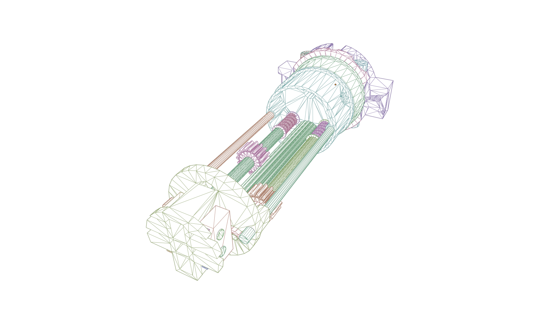
Tessellated result with custom settings - wireframe view
Comparing Results
Comparing the results we can observe the following:
- The
custom-> expert tessellation settings are in absolute units (mm) not as an overall ratio (such as the default tessellation presets).- this means, on smaller detailed parts we can observe a more even distribution of triangle density on the custom result. The default tessellation presets (e.g.
finein this case) generally attribute more resolution to smaller parts compared to larger surface areas.
- this means, on smaller detailed parts we can observe a more even distribution of triangle density on the custom result. The default tessellation presets (e.g.
Mesh and output file (glTF) stats comparison:
| Initial Result (defaults) | Tweaked Result (expert settings) |
|---|---|
| 130,190 triangles | 35,640 triangles |
| 107,732 vertices | 36,272 vertices |
| File size 3.3 MB | File size 1.1 MB |
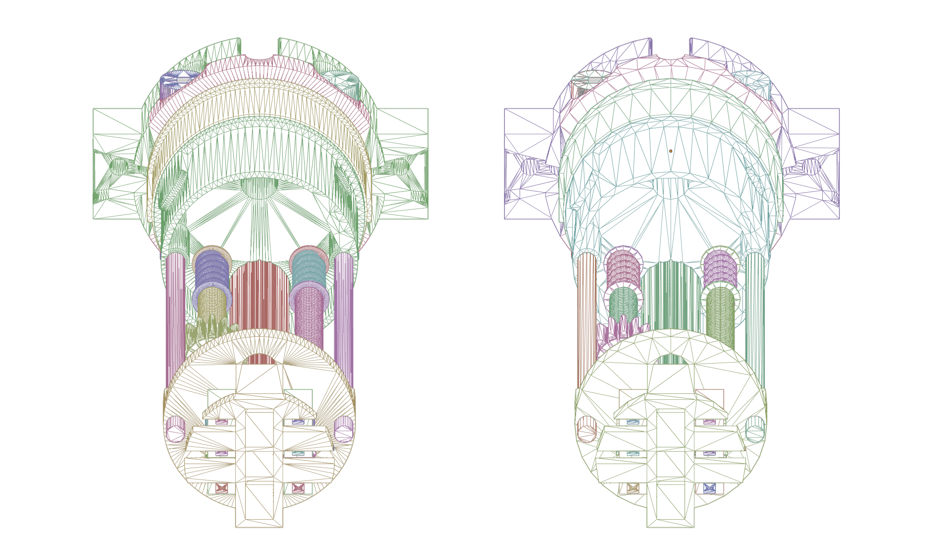
Tessellated results - left: default settings (fine resolution), right: custom settings (maxSurfaceDeviation of 0.2 mm)
As you can see both options can be valid depending on the desired workflow and further planned processing. Also the custom and expert tessellation settings still offer far more options to experiment with. For example we could introduce an additional edge loop on longer shapes such as the streched cylindric rods using maxEdgeLength etc.
Generally we can recommend the following:
- Use
custom+experttessellation settings:- if you are already experienced with CAD to mesh processing and need more customization
- if an overall even face attribution is desired -> in lower resolutions this also can save a lot of triangle count -> recommended for further manual edits and more control
- Use the
defaulttessellation presets:- if you are new to CAD to mesh processing and tessellation
- if the most accurate surface reconstruction is desired without too much tweaking of settings and the overall topology and distribution is not that important -> recommended for further automated optimization processes etc. (decimation, remeshing etc.)